
- 00000018WIA30FC1130GYZ
- id_152711143.1
- Aug 31, 2020 2:56:36 PM
Dock Removal and Reinstallation
Prerequisites
| Required persons | Preliminary requirements | Procedure | Finalization |
|---|---|---|---|
| - | 30 minutes for 450, 750, 450w; 60 to 120 minutes for 450w GEM, 750w GEM | - |
| Item | Quantity | Effectivity | Part number | Manufacturer |
|---|---|---|---|---|
| PPE – safety glasses and gloves | 2 | - | - | - |
| Nonmagnetic Titanium Service Tool Kit, Large Set | 1 | - | 5112581 | - |
| IF NEEDED: Magnet Dock Bolt Cutting Kit | 1 | - | 5435943 | - |
| MCRv Tool Kit | 1 | (For 1.5T) | 5182417 | - |
| MCRv Tool Kit 3.0T | 1 | (For 3.0T) | 5182417-2 | - |
| Item | Quantity | Effectivity | Part number | Manufacturer |
|---|---|---|---|---|
| Masking tape | 1 | - | - | - |
| ||||||||||||||||
About this task
Overview
This document contains procedures to remove and reinstall the patient table dock, which is necessary for replacement of hardware internal to the dock such as switches, motor, and springs.
During this procedures, the following tasks are performed:
- Prepare the dock assembly for removal.
- Cut the anchor stud, if necessary.
- Remove the patient table dock assembly from the magnet room.
- Reinstall the patient table dock assembly.
- Confirm that the patient table dock assembly is installed correctly and the system is working properly and ready to be turned over to the customer.
The dock assembly is the most ferrous object in the magnet room. Utmost care must be taken when following these procedures. Never allow the end of the dock assembly (closest to the magnet) to come off the floor while in the magnet room. During the procedure, you will be asked to lift the front end of the dock assembly; the front end of the dock should never be lifted more than 3 inches (7.6 cm) while in the magnet room.
Preparing Dock for Removal
Procedure
- To assist in repositioning the dock during reinstallation, mark
the placement of the dock on the floor. Depending on the site’s
need, place tape on floor at the leading edge of the dock, and on
the right and left sides. Both are shown in the illustration.
Figure 1. Tape to Mark Original Position of Dock 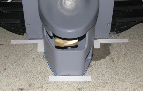
- Visually check the height of the anchor stud that bolts the
dock assembly to the floor. The height of the stud should not exceed
2.75 in (7 cm) as measured from the floor or 2 in (5 cm) as measured
from the top of the clamp bracket.
Figure 2. Measure Height of Anchor Stud 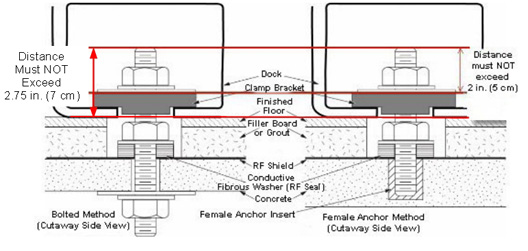
If you do not have something with which to measure the anchor stud, look straight into the opening on the right side of the dock assembly. If you cannot see the top of the stud, the stud is too tall and might need to be cut.
Figure 3. Example of Stud That Must Be Cut 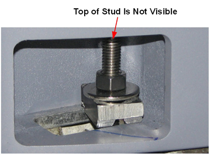
Cutting Anchor Stud
Procedure
At the rear of the dock, use a ¾ inch non-ferrous wrench to LOOSEN (not remove) 4 nuts (2 on each side) from the dock bracket bolts.Notice Figure 4. Dock Brackets 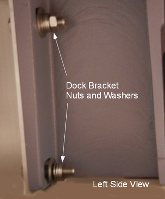
- Cut a small hole in the center of a tack cloth square and fit
it over the top of the stud. The tack cloth will catch and retain
the metal filings as the stud is cut.
Figure 5. Second Nut on Anchor Stud 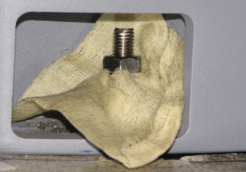
Warning 
CAUTION CAUTION Note:Confirm that the end of the blade extends about 1.5 inches (3.8 cm) beyond the top edge of the hacksaw. This is the portion of the blade that you will use to cut the anchor stud.If the blade on the hacksaw becomes dull during the cutting process, leave the magnet room, disassemble the hacksaw, and flip the blade so a new set of teeth are now cutting the stud.
Figure 6. Extended Blade on Hacksaw 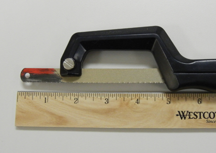
Removing Dock from Magnet Room
Procedure
- Note: Remove only the nuts from the rear of the dock that connect it to the dock brackets. You do not have to remove the dock brackets from the magnet.At the rear of the dock, use a ¾ inch non-ferrous wrench to remove 4 nuts (2 on each side) from the dock bracket bolts. Make note of the number of washers between the dock mounting bracket and the dock at each stud location.
Figure 7. Dock Bracket Nuts and Washers Figure 8. Dock Brackets at Rear of Dock 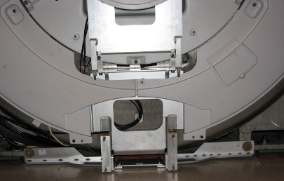
Warning
Applying pressure to the top of the dock, completely remove all dock attachment bolts, then remove washers.Warning 
Make a note of the number of washers that are placed between the dock and the bracket, because they will need to be reinstalled in the same quantities and locations.
See Figure 4 for location of washers and Figure 9 for position of field service personnel when removing hardware.
Note:Remove only the nuts from the rear of the dock that connect it to the dock brackets. Do NOT remove the dock brackets from the magnet.
Figure 9. Apply Pressure to Top of Dock and Remove Bolts 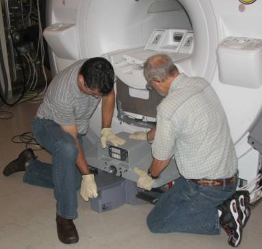
Warning
Use two people to lift the front of the dock JUST ENOUGH to clear the top of the stud in the floor (labeled as 2 in Figure 10). Avoid scraping the dock assembly or the base of the magnet.Warning Do not lift the front of the dock more than 3 inches (7.6 cm) from the floor. The rear of the dock must remain in contact with the floor.
- Use two people to lower the dock back on the floor immediately
to the side of the anchor stud (labeled as 4 in Figure 10).
Figure 10. Pull Dock Away from Magnet, Lift to Clear Stud, Place on Floor to Side of Stud 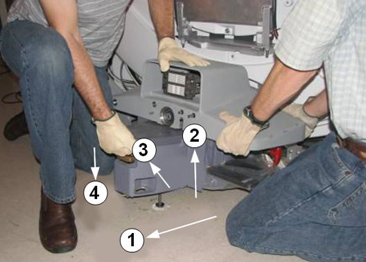
- With two field engineers, one holding each side of the dock,
slowly and deliberately slide the dock away from the magnet, keeping
downward pressure on the top of the dock assembly. Use care as the
loose cables will be trailing behind the dock. Move the dock to a
distance equivalent to where the foot of the patient table would normally
be located.
Figure 11. Apply Pressure to Top of Dock 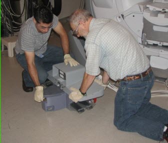
Reinstalling Dock
Procedure
Warning Note:With two field engineers, one holding each side of the dock, enter the magnet room and place the dock on the floor where the foot of the patient table would normally be located.Any time you remove the dock from the magnet, you must check levelness and alignment of the dock and patient table when you reattach the dock to the magnet.
- Position the dock to clear the floor stud. There are two ways
to do this:
- If the site has an anchor stud that protrudes vertically from
the floor and cannot be removed, a non-conformance MUST be raised
with the customer and the anchor must be fixed to comply with the
Pre-Installation Manual before any future servicing of the dock. To
complete the task this time, follow these instructions per the reverse
directions shown in Figure 12.
Figure 12. Positioning Dock When Anchor Stud Cannot Be Removed 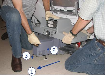
-
While maintaining pressure on the top of the dock, position the dock against the base of the magnet to the side of the floor stud at the front of the dock (number 3).
-
Lift the dock just enough to clear the top of the stud in the floor (number 2).
-
While rotating the dock, align the hole at the base of the dock with the stud and place the dock down into position and re-anchor the dock (number 1).
-
- If the site has an anchor stud that protrudes vertically from
the floor and cannot be removed, a non-conformance MUST be raised
with the customer and the anchor must be fixed to comply with the
Pre-Installation Manual before any future servicing of the dock. To
complete the task this time, follow these instructions per the reverse
directions shown in Figure 12.
- Reattach the nuts and washers to the dock bracket.Note:
Take care with the washers that are placed between the dock and the bracket. Ensure that the same number of washers is installed behind the dock on each bolt.
Figure 13. Dock Brackets 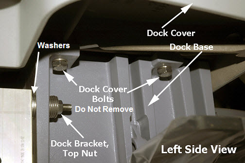
Finalization
Procedure
- Perform all finalization steps required in other referenced procedures.
- Ensure that dock motor on switch operates properly when table up pedal is pressed.
- Perform dock adjustments. See Dock Centering and Dock Hook Tension Adjustment. Confirm proper alignment and centering for the dock and table.
- Verify that cradle travel into the bore is smooth.
- Perform Laser light alignment.
- Perform DQA II Tool and Troubleshooting.
- Perform Check Scan.