
- SIGNA™ Hero 3.0T Service Methods
- 5852800-8EN Revision 1.0
- 00000018WIA30042840GYZ
- id_20147311.18
- Apr 23, 2020 8:47:01 PM
Installing the RF body coil air flow sensor
Install the RF body coil air flow sensor.
Prerequisites
| Personnel requirements | |||
|---|---|---|---|
| Required persons | Preliminary requirements | Procedure | Finalization |
| 1 | - | 60 minutes | 15 minutes |
| Tools and test equipment | |||
|---|---|---|---|
| Item | Quantity | Part number | Manufacturer |
| Nonmagnetic Titanium Service Tool Kit, Large Set | 1 | 5112581 | - |
| Nonmagnetic Titanium Service Tool Kit, Small Set | 1 | 5113258 | - |
| Replacement parts | |||
|---|---|---|---|
| Item | Quantity | Part number | Manufacturer |
| Air Flow Sensor Assembly FRU | 1 | 5604785 | - |
Procedure
- Install the RF body coil air flow sensor housing to the side electronics:Note: The air flow sensor housing is secured to the side electronics with Velcro.
- Attach the air flow sensor housing to the side electronics. If needed, press firmly to secure in place.Note: The airflow sensor must be attached to the right side of the SRI.
Figure 1. Air flow sensor housing 
- Secure the cables.
Figure 2. Cables 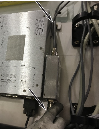
- Connect one end of the RF body coil air flow sensor assembly to SRI J24.
Figure 3. Connect SRI J24 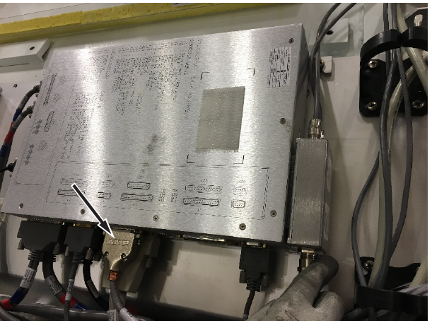
- Zip tie the opposite end of the two cables together and route to the 10:30 position on the patient end.
Figure 4. Cables 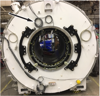
- Attach the air flow sensor housing to the side electronics. If needed, press firmly to secure in place.
- Install the body coil air flow sensor to the patient end:
- Install the two air flow sensor heads.
Figure 5. Air flow sensor heads 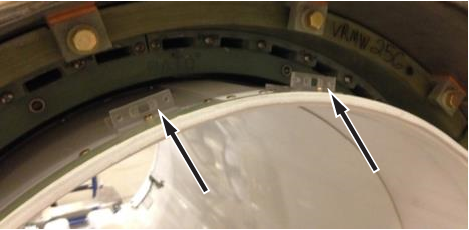
- Secure the four M4 x 10 brass screws.
Figure 6. Brass screws 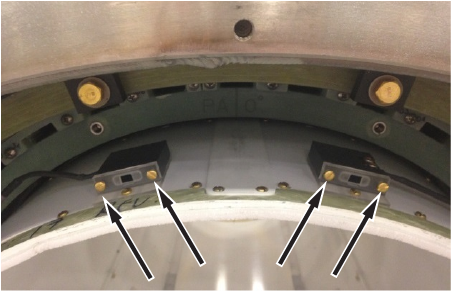
- Install the two air flow sensor heads.