- SIGNA™ Hero 3.0T Service Methods
- 5852800-8EN Revision 1.0
- 00000018WHA30597EGYZ
- id_20028205.7
- Jan 19, 2022 3:33:22 AM
Installing the magnet front cover
Installs the front cover onto the magnet.
Prerequisites
| Personnel requirements | |||
|---|---|---|---|
| Required persons | Preliminary requirements | Procedure | Finalization |
| 2 | - | 30 minutes | - |
About this task
Procedure
- At the front end, align the magnet front cover pins with the large opening of the keyholes on the magnet front cover and place in front of the magnet. Do not lift into place until instructed.
Figure 1. Front cover alignment 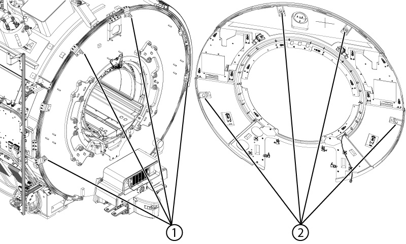
1 Front cover pins 2 Front cover keyholes - Install 16
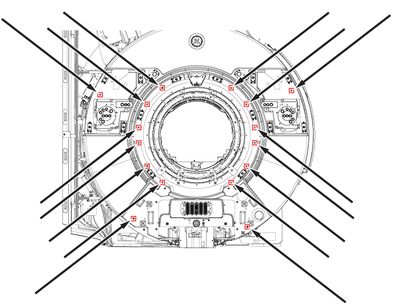
M10 x 25 Socket Head Cap Screws
securing the front cover to the magnet.
Figure 2. Front cover screws