
- SIGNA™ Hero 3.0T Service Methods
- 5852800-8EN Revision 1.0
- 00000018WIA306CB230GYZ
- id_156672361.9
- Jul 13, 2021 4:27:36 PM
FPU Sensor Replacement
Prerequisites
| Required persons | Preliminary requirements | Procedure | Finalization |
|---|---|---|---|
| 1 | Not Applicable | 60 minutes | 15 minutes |
| Item | Quantity | Effectivity | Part number | Manufacturer |
|---|---|---|---|---|
| Standard Tool | 1 | - | - | - |
| Flashlight | 1 | - | - | - |
| 20L Draining Tank (Shipped with System) | 2 | - | - | - |
| Water Hand Pump (Shipped with System) | 1 | - | - | - |
| Draining Hoses (Shipped with System) | 2 | - | - | - |
| Water Shield Tape | As needed | - | - | - |
| Item | Quantity | Effectivity | Part number | Manufacturer |
|---|---|---|---|---|
| Towels | 2 or 3 | - | - | - |
| Item | Quantity | Effectivity | Part number | Manufacturer |
|---|---|---|---|---|
| FPU | 1 | - |
Refer to FRU Manual | - |
| ||||
Procedure
- Open ICC Cover. Note: If Service space is narrow, remove the door.
Figure 1. Remove Cover 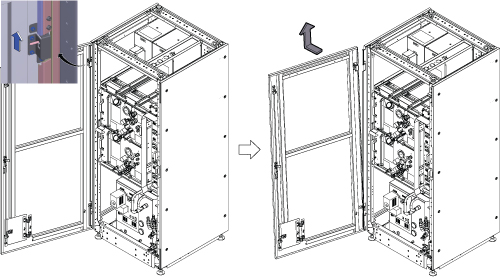
- Remove the bottom reinforcement bar by removing 6 screws.
Figure 2. Remove the bottom reinforcement bar 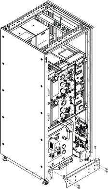
- Turn F50 Power OFF.
- Turn off the “Drive Switch”.
- Turn off the “Main Power Switch”.
Figure 3. F50 Power OFF 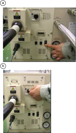
- Close the following valves.
Notice 
Close shut-off valves of FPU.
Figure 4. Close Valves 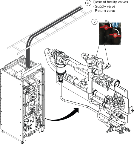
- Drain the ICC primary water circuit to the tank per following steps.
Figure 5. Draining 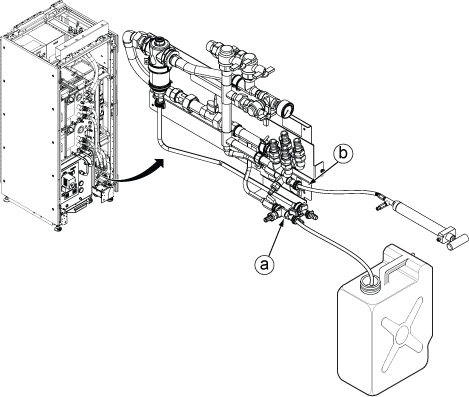
- Close water valves for F-50.
Figure 6. Close F50 valves 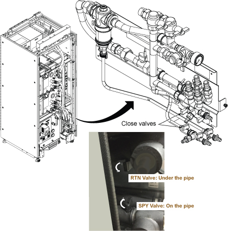
Disconnect F-50 supply and return hoses from the elbow rotating adaptors.Notice Note: While rotating the hex head connector, the hose will also follow the rotation movement. Since the elbow of connector rotate freely, rotate the hose backward as needed.Note: Remaining water in the hose will spill. Prepare towels before disconnecting.Figure 7. Disconnect Hoses 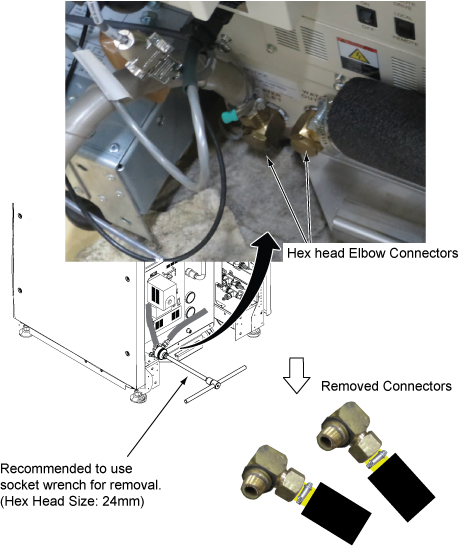
Disconnect the FPU sensor cable connector from 3X11 of Control Unit.Notice Figure 8. Disconnect the FPU sensor cable 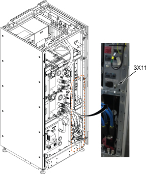
- Disconnect GCU and CCU Quick Disconnects.
Figure 9. Quick Disconnects 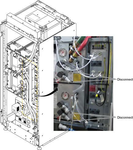
- Close the valves for F–50.
Figure 10. Close valves - Slide out the FPU to access to the FPU sensor per following steps.
- Loosen a captive screw.
- Slide the FPU out from ICC to access to the FPU Sensor.
Figure 11. Slide FPU 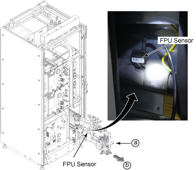
- Remove the sensor according to the following steps.
- Remove the pin which is fixing the sensor.
- Pulling out the sensor to up direction.
Figure 12. FPU Sensor removal 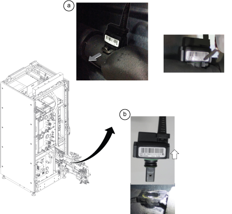
- Confirm the followings before installing new FPU sensor.
-
Water shield o-ring must be at the connector top (border) shown below.
-
Barcode label is the front side when installing.
Figure 13. Confirmation for FPU Sensor 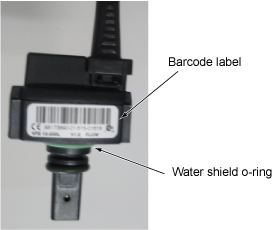
-
- For F-50 water hose connectors (supply and return), remove the remaining shield tape with tool such as precision driver for both connectors. Then, wind the shield tape by two turns.
Figure 14. Shield tape restoration 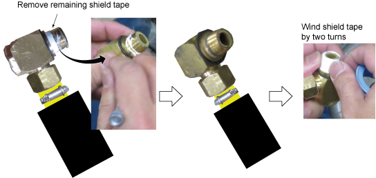
- Open the valves in the following order.Note: Specification of facility water flow is between 50L/min and 80L/min (13.2gpm~21.1gpm) Typical Value of water flow is 60L/min (15.8gpm).
Figure 15. Opening valves 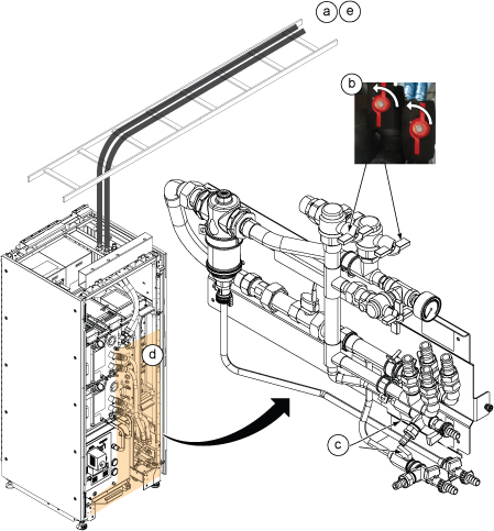
Finalization
- Turn on the F50 cryocooler.
- Turn on the “Main Power Switch”.
- Turn on the “Drive Switch”.
- Turn on ISC Power. Refer to Removing LOTO - ISC.
- Perform Water Flow Adjustment per following steps.
- Insert SSA Service Key.
- Open Common Service Desktop and select .
- Click Run and check Customer Coolant Flow Rate and check if displayed Customer Coolant Flow Rate is in between 50L/min and 80L/min. Note: Typical Value of water flow is 60L/min (15.8gpm)
Figure 16. Cabinet Monitor Functional Diag 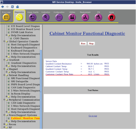
- If the displayed value is between 50L/min and 80L/min, go to next step (3.e)
If coolant flow rate is out of specification, adjust the FPU bypass valve until the coolant flow satisfies the specification.
-
To increase Facility Water Flow : Turn the Bypass valve to Clockwise. Maximum Water Flow when Bypass valve is at Vertical Position.
-
To reduce Facility Water Flow : Turn the Bypass valve to Counter Clockwise. Minimum Water Flow when Bypass valve is at Horizontal position.
Note: Click Run Button of Functional Diag each time when measuring.Figure 17. FPU Bypass valve 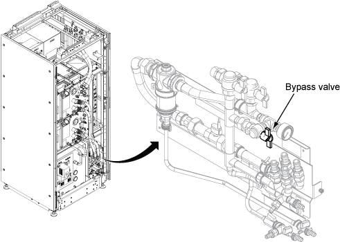
-
- Check the F-50 Water Flow by Magnet Monitor. (Press Data key, then press Down key to show Water_Flow)
Figure 18. Magnet Monitor operation 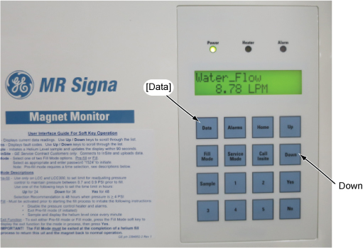
- Adjust the water flow by adjusting the F-50 supply water valve so that water flow becomes within 7~10 L/min. If it’s difficult to adjust the water flow within 7~10 L/min, adjust the water flow by referring to admissible range (water flow vs. water temperature) shown in Figure 20.
Figure 19. F-50 Supply Valve Adjustment 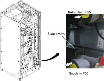
Figure 20. Cryocooler Water Cooling Requirements 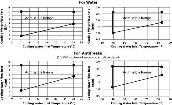
- Perform check scan.