- task_ytj_ygb_qfb
- Version: 4.2
- Date: Feb 28, 2020 3:21:49 PM
Applying LOTO - PEN cabinet (magnet room electronics)
Prerequisites
| Personnel requirements | |||
|---|---|---|---|
| Required persons | Preliminary requirements | Procedure | Finalization |
| 1 | - | 30 minutes | - |
| Tools and test equipment | |||
|---|---|---|---|
| Item | Quantity | Part number | Manufacturer |
| RED Logout Tagout Lock with Each Lock Uniquely Keyed | 1 | 5451778 | - |
| Multi-Locking Device (if multiple service personnel are involved) | 1 | 46-194427P313 | - |
| Red Warning LOTO Tag | 1 | 46-194427P322 | - |
| Digital Voltmeter (DVM) | 1 | 46-194427P284 | - |
| Safety |
|---|
|
Before working in any GE Healthcare MR suite or performing any GE Healthcare service procedure, you must:
If you have any safety concerns at any time, do not begin work or immediately stop work and move to a safe location. Immediately contact your supervisor or site safety officer for instructions on how to proceed. |
|

- There are two types of PDUs/PGR Cabinets. The LOTO steps are the same, but the physical components are slightly different.
- This procedure does not cover the Gradient Filter. For LOTO requirements of the Gradient Filter, refer to LOTO for the PGR PDU/Gradient Subsystem.
| Affected by LOTO | ||||
|---|---|---|---|---|
| Name of equipment | Number of locks | Titles of employees authorized to perform LOTO | Titles of affected employees | How to notify |
Examples of RF Subsystem components
Examples of Pen Cabinet Electronics
Examples of Magnet Room Electronics
|
1 per GE Field Engineer (FE) | GE Field Engineers | Hospital Personnel | Verbal, Posted signs |
| Energy source | Yes | No | Location of energy | Magnitude/type of energy |
|---|---|---|---|---|
| Electrical | x | Power, Gradient, RF Cabinet (PGR) PDU (power distribution unit) Circuit Breaker Panel | 208 VAC | |
| Pneumatic | x | |||
| Hydraulic | x | |||
| Gas/Water/Steam | x | |||
| Chemical | x | |||
| Mechanical Motion | x | |||
| Gravity | x | |||
| Springs | x | |||
| Thermal | x | |||
| Stored Energy | x | Time discharge of internal capacitors | 170 VDC | |
| Air Under Pressure | x | |||
| Oil Under Pressure | x | |||
| Water Under Pressure | x | Heat Exchanger Cabinet (HEC) PGR Pump Circuit Breaker (PPMPCB) and RF amp quick disconnect | 5.0 Bar (80 psi) | |
| Gas Under Pressure | x | |||
| Steam | x | |||
| Other | x |
Procedure
- Notify affected personnel working in the area that LOTO is being performed.
- Make sure the host computer is shut down.
- Make sure the SRPS, PHPS, or eSRPS LEDs are lit to confirm power is on.
Figure 1. PEN cabinet LEDs on (SRPS)
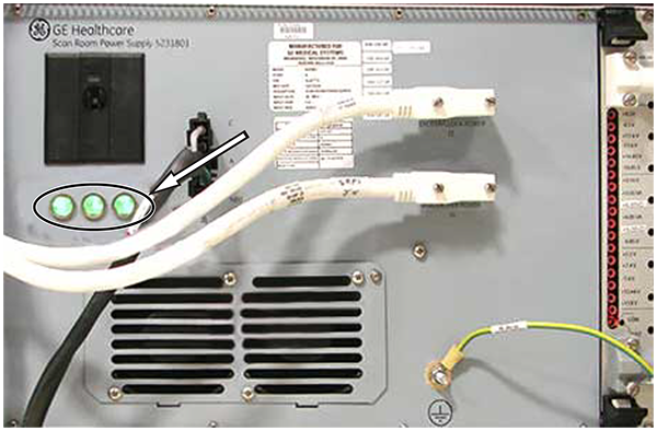
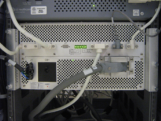
Figure 2. PEN cabinet LEDs on (eSRPS)
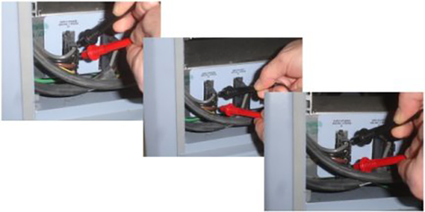
- At the front panel of the PDU, switch the PDM-RF (or PEN Cabinet) circuit breaker to the OFF (down) position.
Figure 3. Old style PEN cabinet circuit breaker
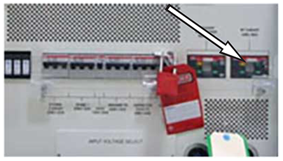
Figure 4. New style PEN cabinet circuit breaker
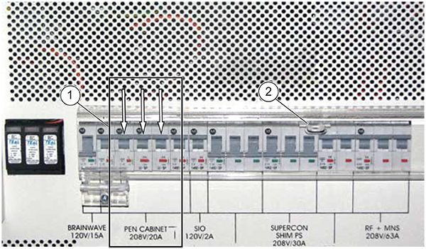
1 Circuit breaker 2 Apply personal LOTO device - At the front panel of the PDU covering the circuit breakers, apply a personal LOTO device for each FE working on the equipment.
- Make sure power is OFF. Look at the SRPS or PHPS LEDs to visually confirm that the power is OFF. See Figure 1 or Figure 2.
If the LEDs are on, confirm RF Subsystem/PEN Cabinet is in the OFF position.
- Make sure all energy has dissipated. Measure the voltage at the Power Distribution Module incoming AC connector and confirm 0 volts.note: The PHPS power switch LED is off when the voltage is dissipated.
Figure 5. PGR power distribution module terminal board (if present)