- id_19633183
- Version: 4.3
- Date: Dec 6, 2019 11:53:35 AM
Applying LOTO - PGR PDU/Gradient Subsystem
Prerequisites
| Personnel requirements | |||
|---|---|---|---|
| Required persons | Preliminary requirements | Procedure | Finalization |
| 1 | - | 10 minutes | - |
| Tools and test equipment | |||
|---|---|---|---|
| Item | Quantity | Part number | Manufacturer |
| RED Logout Tagout Lock with Each Lock Uniquely Keyed | 1 | 5451778 | - |
| Multi-Locking Device (if multiple service personnel are involved) | 1 | 46-194427P313 | - |
| Red Warning LOTO Tag | 1 | 46-194427P322 | - |
| Digital Voltmeter (DVM) | 1 | 46-194427P284 | - |
| Safety |
|---|
|
Before working in any GE Healthcare MR suite or performing any GE Healthcare service procedure, you must:
If you have any safety concerns at any time, do not begin work or immediately stop work and move to a safe location. Immediately contact your supervisor or site safety officer for instructions on how to proceed. |
|

|
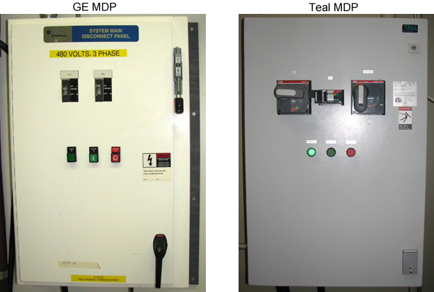
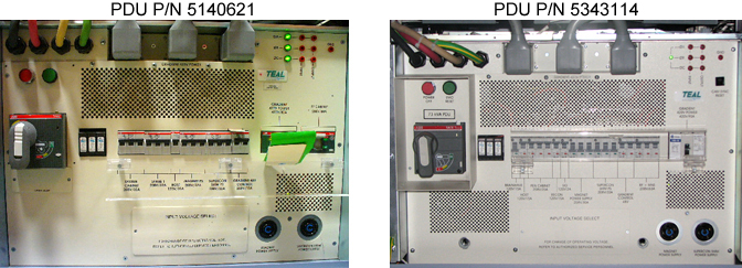
note: GE Healthcare supplies two types of MDPs (GE and teal) and two types of PDUs (5140621 and 5343114). The LOTO steps are the same, but the physical components are slightly different. Customers have the option of supplying their own MDPs.
MR750w systems have only the teal MDP (if the MDP is supplied by GE Healthcare) and PDU 5343114.
| Affected by LOTO | ||||
|---|---|---|---|---|
| Name of equipment | Number of locks | Titles of employees authorized to perform LOTO | Titles of affected employees | How to notify |
| All MR equipment | 1 per GE field engineer (FE) | GE Field Engineers | Hospital personnel | Verbal, posted signs |
note: The following table describes the type, location, and magnitude of energy to be LOTO’d.
| Energy Source | Yes | No | Location of Energy Isolating Means | Magnitude of Energy |
|---|---|---|---|---|
| Electrical | x | PGR PDU circuit breaker panel, Main Disconnect Panel (MDP) circuit breaker panel | 208 VAC, 420 VAC, 380-480 VAC | |
| Pneumatic | x | |||
| Hydraulic | x | |||
| Gas/Water/Steam | x | |||
| Chemical | x | |||
| Mechanical Motion | x | |||
| Gravity | x | |||
| Springs | x | |||
| Thermal | x | |||
| Stored Energy | x | Time discharge of internal capacitors | 208 VAC, 420 VAC | |
| Air Under Pressure | x | |||
| Oil Under Pressure | x | |||
| Water Under Pressure | x | Heat Exchanger Cabinet (HEC), PGR Pump Circuit Breaker (PPMPCB) and RF amp quick disconnect | 5.0 Bar (80 psi) | |
| Gas Under Pressure | x | |||
| Steam | x | |||
| Other | x |
Types of equipment and/or methods selected to dissipate or isolate stored energy
Type(s) of equipment and/or method(s) used to ensure disconnection(s)
- A personal lock and tag per Field Engineer (FE) at the site working on the de-energized equipment at the time of LOTO.
- Voltmeter to read voltage for verification that energy has dissipated in the PDU.
Procedure
- Notify affected personnel that LOTO will be applied.
- At the Operator Workspace, shut down the Host PC.
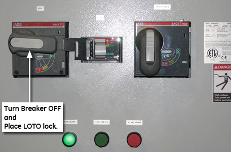
- Locate and turn off the PGR PDU main breaker on the Main Disconnect Panel (MDP) that feeds the PGR cabinet.note: If the system uses a customer-supplied MDP, see the MDP manual for information about how to lock out/tag out the PDU breaker.
- Lock Out/Tag Out the PDU breaker on the MDP.
Figure 1. PDU breaker on an GE MDP
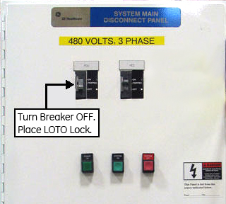
Figure 2. PDU breaker on teal MDP
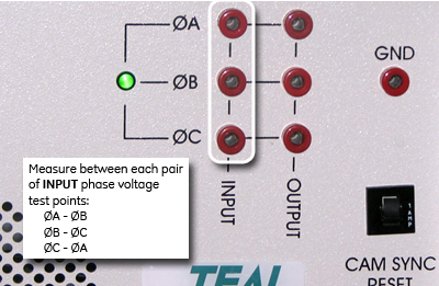
- Make sure all energy has been dissipated. Use a voltmeter to measure the line-to-line voltage between each INPUT phase voltage test point on the PDU.The PDU main breaker must be in the ON position to read accurate voltage on the test points.note: The test points are 100:1 ratio (480 VAC = 4.80 VAC, 208 VAC = 2.08 VAC). Therefore, a low voltage reading still indicates the presence of high voltage. Your voltage reading for each of the three phases must be 0 VAC before proceeding.
- Input Voltage Range: 380 - 480 VAC = 3.8 - 4.8 VAC
- Output Voltage Range: 208 VAC = 2.08 VAC
Figure 3. PDU test points (PDU 5140621)
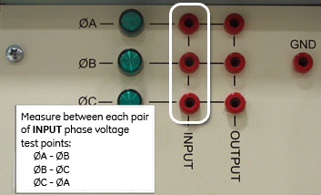
Figure 4. PDU test points (PDU 5343114)