- id_12374186
- Version: 1.16
- Date: Feb 27, 2020 4:57:36 PM
Removing the exciter
Remove the exciter.
Prerequisites
| Personnel requirements | |||
|---|---|---|---|
| Required persons | Preliminary requirements | Procedure | Finalization |
| 1 | - | 20 minutes | - |
| Tools and test equipment | |||
|---|---|---|---|
| Item | Quantity | Part number | Manufacturer |
| Standard Hand Tools | 1 | - | - |
|

 |
|
|
 |
|
Overview
This procedure describes how to replace the single drive or dual drive digital exciter (DTX1) module located in the PEN cabinet. Order the correct DTX1 exciter replacement for the site’s system.
The exciter with Fiber optic output is compatible on systems with CAM and on DV systems with ICE and RRX receivers using a clock splitter. The exciter with electric clock is only compatible on Artist/Artist XT, Architect/Architect XT, and later systems.
Procedure
- Loosen the thumbscrews that secure the exciter to the PEN cabinet.
Figure 1. Exciter with fiber optic clock outputs
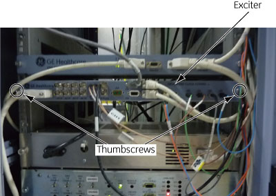
Figure 2. Exciter with electronic clock output
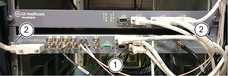
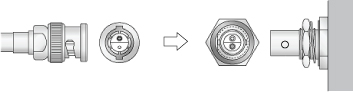
1 Exciter 2 Thumbscrews - note: Clock cables on the exciter are Twin BNC connector cables. Align pins and keys before connection after replacement.Disconnect all the cables to the exciter. Note all the cable locations for reconnection. There are connections on both the front and back of the exciter.
- Carefully slide the exciter out of the PEN cabinet.