- id_12373879
- Version: 1.9
- Date: Feb 20, 2020 9:33:20 AM
Scan Room Blower Box Replacement
Prerequisites
| Required persons | Preliminary requirements | Procedure | Finalization |
|---|---|---|---|
| 2 | Not Applicable | 30 minutes | Not Applicable |
| Item | Quantity | Effectivity | Part number | Manufacturer |
|---|---|---|---|---|
| Non-magnetic tool set | 1 | - | - | - |
| Item | Quantity | Effectivity | Part number | Manufacturer |
|---|---|---|---|---|
| Cable ties (standard 4-6 inch) | - | - | - | - |
| Electrical insulating tape | - | - | - | - |
| Item | Quantity | Effectivity | Part number | Manufacturer |
|---|---|---|---|---|
| Dual blower box | 1 | RRx receive chain systems |
5213397–100 |
- |
| Single blower box | 1 | DPP receive chain systems |
5213397–200 |
- |
|
| Condition | Reference | Effectivity |
|---|---|---|
|
All persons performing this procedure must complete GE-certified MR safety training. |
- | - |
Power Down and LOTO
Procedure
 danger
- Perform LOTO on the PEN cabinet. See the MR Service Safety Manual, PN 5452735.
 |
Removing Blower Box
Procedure
- Allow five minutes for the filters to discharge. After five minutes, check capacitors for discharge with grounded cable on DVM.
- Remove any cable ties on the blower box power cable.
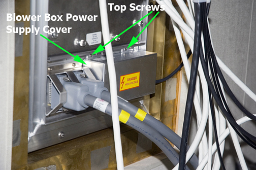
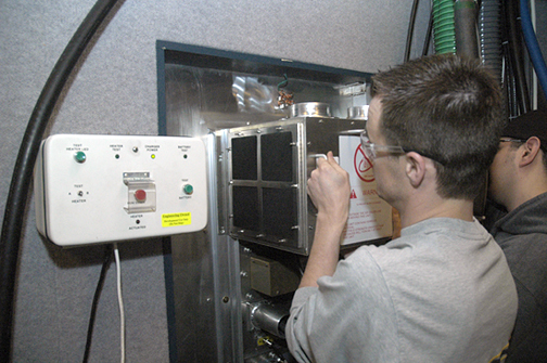
- In the magnet room, remove the two top screws and two bottom
screws from the blower box power supply cover on the lower right corner
of the PEN panel.
Figure 1. Blower Box Power Supply Cover
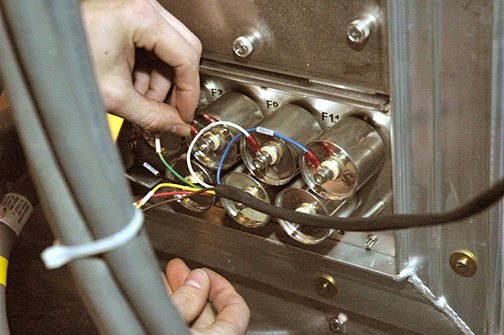
- Be sure the power cables are properly marked or labeled for
later reconnection. Disconnect the power cable connectors from the
AC power filters. See Table 7for a list of cables and connections.note:
The single blower box has five power cables. The dual blower box has seven power cables.
Figure 2. AC Power Filters
- Follow the cable path and confirm that the cable is free of the penetration wall and will not tangle when the blower box is removed.
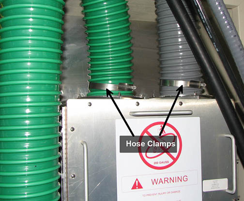
- Remove both air hoses at the top of the blower box.
Systems with the RRx receive chain use the dual blower box, which uses two hoses to provide air for both patient comfort and the RF hub. Systems with the DPP receive chain do not have the RF hub and use the single blower box, which uses one hose to provide patient air only.
note:Mark or label the two air hoses at the top of the blower box to note their mounting location.
Figure 3. Air Hose Clamps
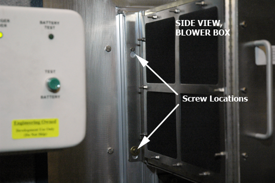
- note:Loosen, but do not remove, the four screws securing the blower box to the PEN panel.
Some sites have a closet service hatch installed in the scan room wall. Use the closet service hatch to safely remove the blower box from the scan room.
note:If the slot on the mounting flange does not provide enough clearance for placing over the existing flange studs, remove the mounting screws, position the blower box on the SPW, and attach with the removed screws.
At least two people are required for this procedure.
Figure 4. Side View of Blower Box
- danger
- warning
- notice
- With two people holding the blower box, exit the magnet room by walking as close to the wall on the coldhead side of the magnet as possible. See Figure 5.
 |
Installing New Blower Box
The following steps explain how to install the scan room blower box. If you are performing this procedure as part of a upgrade from an RRx receive chain system to a DPP receive chain system, you should reuse the dual blower box from the RRx system but disable the unused RF hub air blower function. See Step 4.
Procedure
- With two people holding the blower box, stay as far away from
the magnet as possible as you bring the blower box into the magnet
room and position it on the PEN panel. See Figure 5. Refer to note inStep 8 above to determine safe distance.note:
Some sites have a closet service hatch installed in the scan room wall. Use the closet service hatch to safely insert the blower box into the scan room.
- With two people, lift and slide the blower box mounting holes
over loosened screws on the PEN panelnote:
If you had to remove one or more of the screws during the removal process, one person must hold the blower box in place while the second person installs the screws.
- With one person holding the box in place, tighten the four screws
to secure the blower box to the PEN panel frame.
Figure 5. Mounting New Blower Box
- warning
- Attach the blower box power
cable to the power supply panel filters, matching the labels on each
connector to its corresponding filter. If you are performing this
procedure as part of an upgrade from an RRx to a DPP receive chain
system, disable the unused RF hub air blower by reconnecting all of
the cables except the two that are labeled PEN-F5 and PEN-F6. Bend the PEN-F5 and PEN-F6 wires
back against the length of the power cable jacket. Secure the wires
by wrapping electrical tape around the eyelet terminals to prevent
electrical contact with the AC power filter connections.important: Arc flash may occur if exposed terminals contact AC power filter connections.note:
There should be a washer above and below each ring terminal on the filter stud.
Figure 6. AC Power Filter Cable Connections
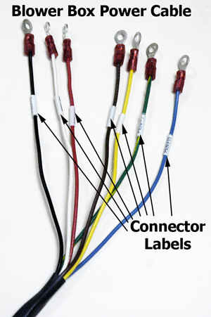
Figure 7. AC Power Filter Cable Connections for DPP
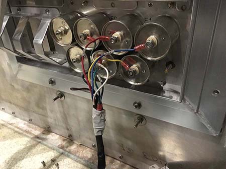
Table 7 Cables and Connections Power cable color
PEN panel AC power connection
Blower type (single, dual, or both)
Blue
PEN-F11
Both
Yellow
PEN-F10
Both
Red
PEN-F9
Both
White
PEN-F8
Both
Green and yellow
PEN-F7
Both
Brown
PEN-F6
Dual blower only
Black
PEN-F5
Dual blower only
- Replace the power supply cover. Ensure the cable is routed through
the cable access hole, and is not pinched under the cover. The warning
label should be upright.note:
The length of the power cable from the bottom of the blower box to the power supply filter panel provides enough slack to run the cable along the right side of the PEN panel using cable ties to hold the cable in place.
- Replace the air hose connections, noting the correct location. Secure the air hose by tightening the worm gear hose clamps. Pull on each hose to confirm the hose is securely fastened to the blower box.
Finalization
Procedure
- Remove LOTO from the PEN cabinet. See the MR Service Safety Manual, PN 5452735.
- Ensure air is flowing to the patient bore.
- (For systems equipped with the legacy RF hub) : Ensure air is flowing to the RF hub.