Prerequisites
Table 1 Personnel requirements| Required persons |
Preliminary requirements |
Procedure |
Finalization |
|---|
| 1 |
Not Applicable |
15 minutes |
Not Applicable |
Table 2 Tools and test equipment| Item |
Quantity |
Effectivity |
Part number |
Manufacturer |
|---|
| Standard Hand
Tools |
1 |
- |
|
- |
Table 3 Replacement parts| Item |
Quantity |
Effectivity |
Part number |
Manufacturer |
|---|
| Clock Splitter |
1 |
- |
See FRU Manual
|
- |
Table 4 Safety
|  danger danger
- FATAL ELECTRIC SHOCK HAZARD!
- Fatal voltages exist throughout the cabinet when energized.
- TO PREVENT FATAL ELECTRIC SHOCK, DISCONNECT POWER FROM
THE PDU BEFORE continuing. PERFORM LOTO procedures PER GE REQUIREMENTS.
See the MR Service Safety Manual, PN 5452735.
|
| - Potential component damage
- Electrostatic discharge (ESD) can cause permanent damage to electronic components.
- Observe the following ESD precautions:
- Work on a static-free mat.
- Wear a static strap to ensure that any accumulated electrostatic charge is discharged from your body to the ground.
- Create a common ground for the equipment being worked on by connecting the static-free mat, static strap, and peripheral units to that piece of equipment.
|
|
Overview
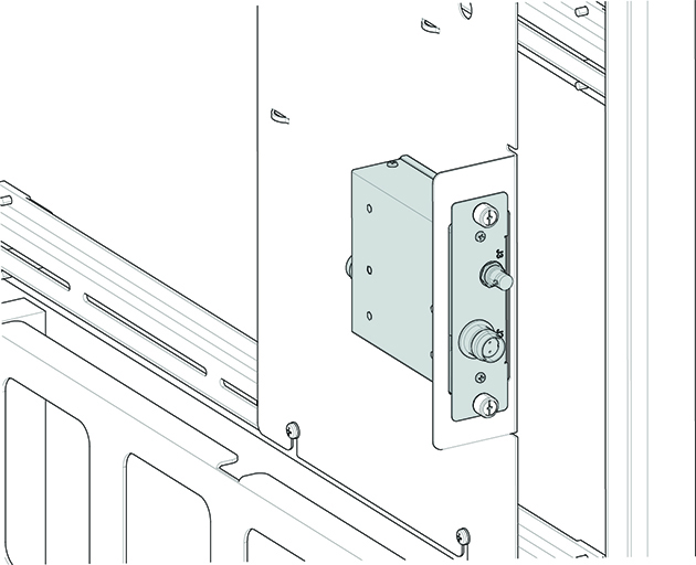
This procedure describes how to replace the clock splitter in
the PEN cabinet. The clock splitter exists in RRX receiver systems
with ICE or in systems upgraded to ICE.