- id_12373302
- Version: 1.3
- Date: Jul 5, 2019 6:08:28 PM
SRPS and eSRPS Unit and Fan Replacement
Prerequisites
| Required persons | Preliminary requirements | Procedure | Finalization |
|---|---|---|---|
| 1 | Not Applicable | 2 hours | 20 minutes |
| Item | Quantity | Effectivity | Part number | Manufacturer |
|---|---|---|---|---|
| Hoist Service Kit (service tool needed for complete SRPS replacement only) | 1 | - |
5196226 |
- |
| Non-Magnetic Tool Kit (or equivalent) | 1 | - |
5112581 |
- |
| Item | Quantity | Effectivity | Part number | Manufacturer |
|---|---|---|---|---|
| SRPS Unit | 1 | - |
See FRU Manual |
- |
| eSRPS Unit | 1 | - |
See FRU Manual |
- |
| SRPS Control Board Assembly | 1 | - |
See FRU Manual |
- |
| Fan for SRPS or eSRPS | 1 | - |
See FRU Manual |
- |
note:
An open (bad) fuse indicates a catastrophic failure. Do not replace the fuse. Replace the SRPS. |


Overview
This document describes the procedure for replacing the Scan Room Power Supply (SRPS) and EcoPower Scan Room Power Supply (eSRPS).
Because of its weight, removing the SRPS from the PEN cabinet requires you to use the hoist service tool. The hoist service tool allows one person to perform this procedure. This is the preferred method to avoid injury.
The eSRPS is light enough to be removed by one person without the use of a hoist.
This procedure also describes fan replacement for both the SRPS and eSRPS.
| SRPS | eSRPS |
|
|
| SRPS Procedures | eSRPS Procedures |
SRPS Replacement
SRPS Removal
Procedure
- Perform LOTO on the PEN cabinet. See the MR Service Safety Manual, PN 5452735.
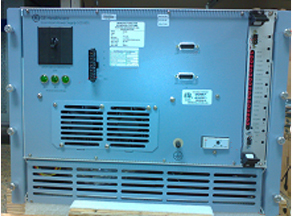
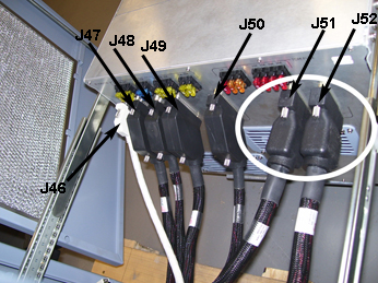
- Remove the cables from the front of the SRPS.
Figure 1. SRPS Front
- Loosen the 8 thumb screws on the front of the SRPS.
- Set up the hoist service tool according to Hoist Service Kit and Lifting Accessories.
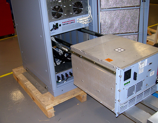
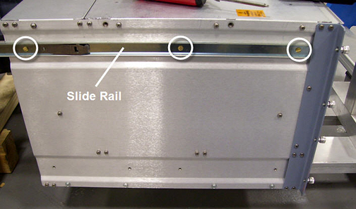
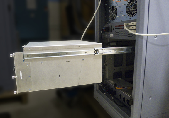
- Pull the SRPS out from the PEN cabinet until the slide rails
lock into position.
Figure 2. Pull Out SRPS
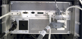
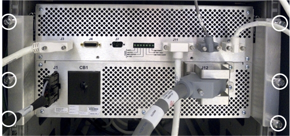
- Remove the cables from the rear of the SRPS.
Figure 3. SRPS Rear with J51 and J52 Highlighted
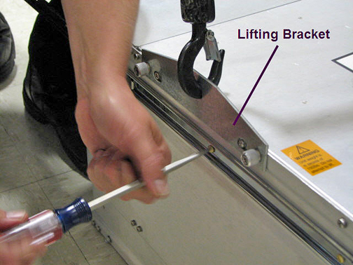
- Attach a lifting bracket from the FRU container to each side
of the SRPS.
Figure 4. Attach Lifting Brackets
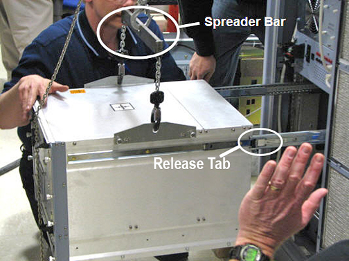
- Attach the spreader bar (hoist kit) to the lifting brackets.
Attach the spreader bar to the hoist chain.
Figure 5. Spreader Bar - Hoist Kit
- Ratchet the winch to tighten the hoist chain.
Before putting weight on the hoist chain, be sure that the links are aligned properly. This helps keep the chain from binding up, or becoming kinked, which is nearly impossible to correct when the chain is under tension.
- Press the release tab and pull out the SRPS to release it from the rail.
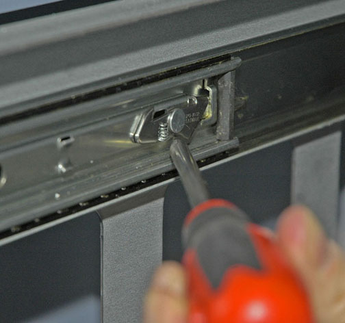
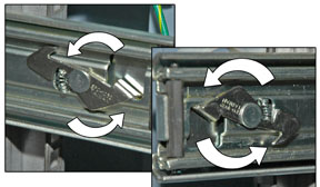
- Release the PEN cabinet outer slide rails and slide them back
into the cabinet.
You may want to use a screwdriver to release the outer slide rail.
Figure 6. Release Outer Slide Rail Locking Levers
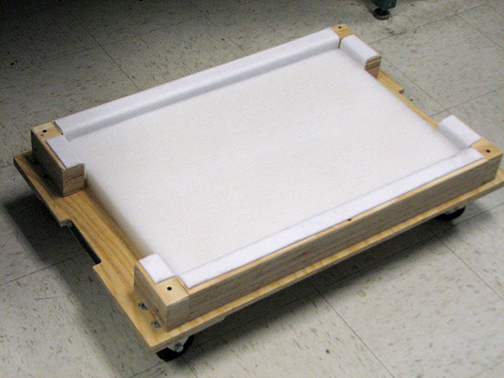
- Lower the SRPS onto the FRU packaging platform for removal.
Figure 7. SRPS FRU Packaging
- Loosen the hoist chain and remove the spreader bar.
- Remove the lifting brackets.
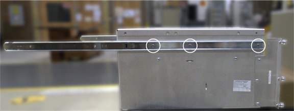
- Remove both slide rails from the SRPS.
Figure 8. Remove Slide Rails
- If present, remove the dongle from J50 of the failed SRPS unit to transfer to the new SRPS unit.
SRPS Replacement
Procedure
- note:Attach both slide rails to the new SRPS.
After the SRPS is replaced, the final system configuration should have a dongle (5172838-2) on the new SRPS at J50, or on the PEN panel at J50 from the magnet room side.
- Attach both lifting brackets to the new SRPS. See Figure 4.
- Attach the spreader bar (hoist kit) to the lifting brackets. Attach the spreader bar to the hoist chain. See Figure 5.
- Ratchet the winch to tighten the hoist chain and begin lifting the SRPS.
- Slide out the PEN cabinet slide rails a short distance to see how high to lift the module.
- notice
- After the SRPS is aligned with the outer rails, pull out each PEN cabinet outer slide rail fully, until each locks into position.
- Attach the cables to the rear of the SRPS. See Figure 3. Ensure that J51 and J52 are installed correctly.
- Loosen the chain tension with the winch.
- Remove the spreader bar from the lifting brackets.
- Remove the lifting brackets.
- Press the release tab on each rail and carefully slide the SRPS completely into the PEN cabinet slide rails until they lock into position.
- Tighten the 8 thumb screws on the front of the SRPS.
- Refer to the Finalization section for checkout and proper operations.
 |
SRPS Fan Replacement
Procedure
- Perform LOTO on RF and PEN cabinets. See the MR Service Safety Manual, PN 5452735.
- Determine which fan you are replacing (see Figure 9 and Figure 10).
-
If replacing fan 5 or 6 (front fans), see Replacing Front Fans.
-
If replacing fan 1, 2, 3, or 4 (rear fans), see Replacing Rear Fans.
note:If replacing fan 1, 2, 3, or 4, use the lifting fixture and remove the SRPS from the cabinet. Service access to fans is restricted when the power supply is left on the rails; fan replacement is possible but difficult.
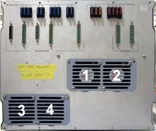
Figure 9. SRPS Front Fans
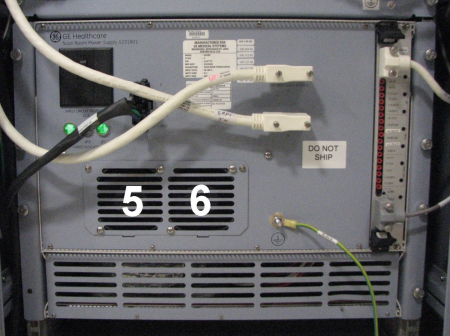
Figure 10. SRPS Rear Fans
-
Replacing Front Fans
Procedure
- Remove the top 2 screws from the fan cover.
Figure 11. Removing Fan Cover
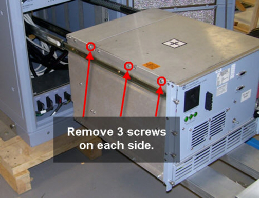
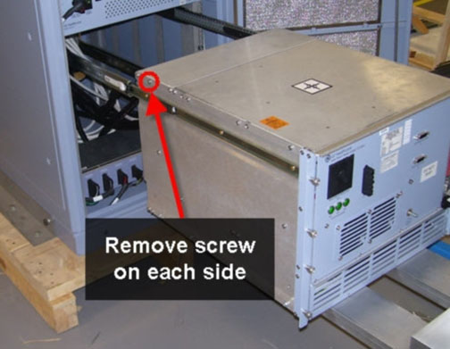
- Disconnect the appropriate cable using quick release. If you
are unable to access the cable, first disconnect all cabling routed
to the front of the SRPS. Then, remove the top cover by sliding the
SRPS out of the cabinet and removing 3 screws on each side.
Figure 12. Removing Top Cover from Front End of SRPS
- Remove the fan assembly from the fan cover by removing 2 screws.
Figure 13. Removing Fan Assembly
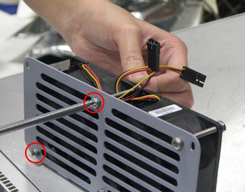 note:
note:Pay careful attention to the label orientation on the fan. When installing the new fan, verify that the label is in the same orientation.
- Install the new fan.
- Reconnect all cabling appropriately.
- Replace all covers.
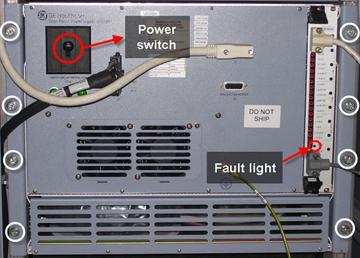
- Restore power. See the MR Service Safety Manual, PN 5452735.
- Check the Fault light on the SRPS to verify that it is not lit.
If the Fault light is lit, check all cable connections.
- Refer to the Finalization section for checkout and proper operation.
Replacing Rear Fans
Procedure
- Disconnect all cables routed to the front of the SRPS. See Figure 1.
- Slide the SRPS completely out of the PEN cabinet by removing 8 thumb screws.
- note:Disconnect the cable connections in the rear to access the fans.
When replacing fan 1, 2, 3, or 4, use the lifting fixture and remove the SRPS from the cabinet. Service access to fans is restricted when the power supply is left on the rails; fan replacement is possible but difficult.
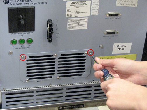
- Remove the top 2 screws from the fan cover.
- Disconnect the appropriate cable using quick release. If you
are unable to access the cable, remove the top cover by loosening
a screw on each side.
Figure 14. Removing Top Cover from Back of SRPS
- Remove the fan assembly from the fan cover by removing 2 screws.
An example is shown in Figure 13.
Pay careful attention to the label orientation on the fan. When installing the new fan, verify that the label is in the same orientation.
- Install the new fan.
- Reconnect all cabling appropriately
- Replace all covers.
- Restore power and remove LOTO from RF/PEN cabinets. See the MR Service Safety Manual, PN 5452735.
- Check the Fault light on the SRPS to verify that it is not lit.
If the Fault light is lit, check all cable connections.
- Refer to the Finalization section for checkout and proper operation.
eSRPS Replacement
eSRPS Removal
Procedure
- Perform LOTO on the PEN cabinet. See the MR Service Safety Manual, PN 5452735.
- Remove the cables from the front of the eSRPS.
Figure 15. eSRPS Front
- Loosen the 6 thumb screws on the front of the SRPS.
- Pull out the eSRPS from the PEN cabinet until the slide rails
lock into position.
Figure 16. Pull Out eSRPS
- Press the release tabs and pull out the eSRPS to release it from the rails.
- Remove both slide rails from the eSRPS.
Figure 17. Remove Slide Rails
eSRPS Replacement
Procedure
- Install the slide rails on the new eSRPS unit.
- Connect the eSRPS rails to the mounting rails in the PEN cabinet, and slide the eSRPS into the cabinet.
- Use the thumbscrews on the front of the eSRPS to secure the unit to the cabinet mounting rails.
- Connect the cables to the front of the eSRPS.
- Restore power to the PEN cabinet. See the MR Service Safety Manual, PN 5452735.
eSRPS Fan Replacement
Procedure
- Perform LOTO on the PEN cabinet. See the MR Service Safety Manual, PN 5452735.
- Remove the eSRPS from the PEN cabinet. See eSRPS Removal.
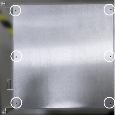
- Remove the top cover of the eSRPS by removing the screws securing
it to the power supply.
Figure 18. eSRPS Top Cover Screw Locations
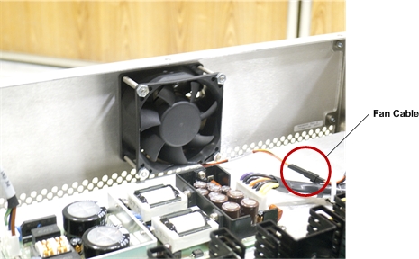
- Disconnect the fan cable.
Figure 19. eSRPS Fan Cable
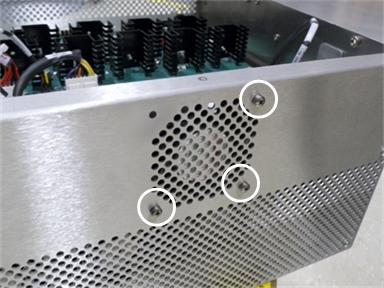
- Remove the screws securing the fan to the rear of the eSRPS.
Figure 20. eSRPS Fan Screws
- Attach the new fan to the inside rear of the eSRPS.
- Connect the fan cable. See Step 4.
- Attach the top cover of the eSRPS with screws.
- Install the eSRPS in the PEN cabinet. See eSRPS Replacement.
- Restore power to the PEN cabinet. See the MR Service Safety Manual, PN 5452735.
Finalization
Procedure
- After replacing the unit, perform a quick scan to ensure proper functionality.
- After fan replacement, check the error log to verify that there is no longer a fan failure.