- id_12374934
- Version: 1.4
- Date: Jul 5, 2019 6:08:29 PM
Driver Module Replacement
Prerequisites
| Required persons | Preliminary requirements | Procedure | Finalization |
|---|---|---|---|
| 1 | Not Applicable | 2 hours | 20 minutes |
| Item | Quantity | Effectivity | Part number | Manufacturer |
|---|---|---|---|---|
| Adjustable Wrench (for hoist brackets) | 1 | - | - | - |
| Small Phillips Screwdriver | 1 | - | - | - |
| Non-magnetic Slotted Screwdriver | 1 | - | - | - |
| Hoist Service Kit (Tool) | 1 | - |
5196226 |
- |
| Item | Quantity | Effectivity | Part number | Manufacturer |
|---|---|---|---|---|
| Driver Module | 1 | - |
5160446-2 |
- |
|


Overview
This document describes the procedure for replacing the driver module. The driver module weighs approximately 50 pounds, so a hoist service tool is required to remove it from the PEN cabinet. The hoist service tool allows one person to safely perform this procedure.
Removing Driver Module
Procedure
- notice
- Perform LOTO on the PEN cabinet. See the MR Service Safety Manual, PN 5452735.
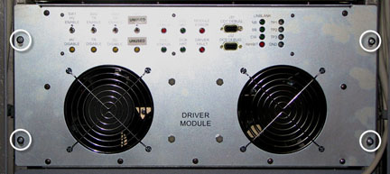
- Remove the four screws securing the driver module to the PEN
cabinet frame.
Figure 1. Driver Module - Rear
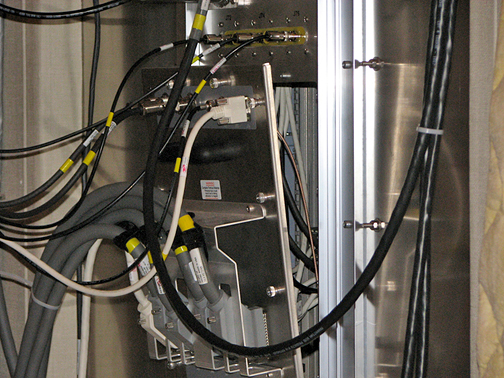
- Loosen the 16 thumbs screws securing the penetration panel to
the magnet room wall. This allows access to the rear of the driver
module.
Figure 2. Removing the Penetration Panel
- Carefully pull the penetration panel away from the wall, leaving all cables attached to the panel.
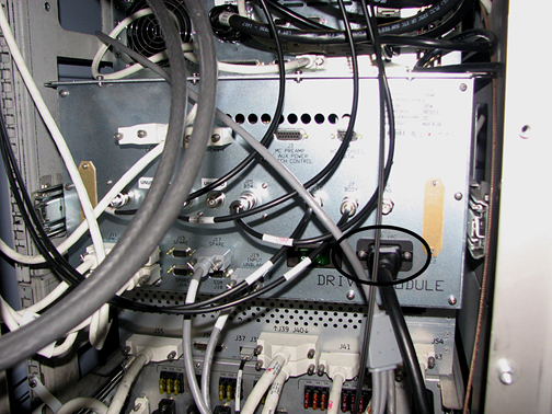
- Remove the cables from the rear of the driver module. note:
Remove screws to access the PWR cable. Be careful not to drop them, they are very small.
Put the screws back in when the PWR CBL is removed.
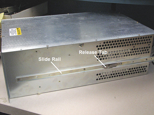
Figure 3. Driver Module - Rear
- Push the driver module forward a little, from the pen wall side.
- Set up the hoist service tool according to Hoist Service Kit and Lifting Accessories.
- Pull the driver module out from the cabinet until the slide rails lock into position.
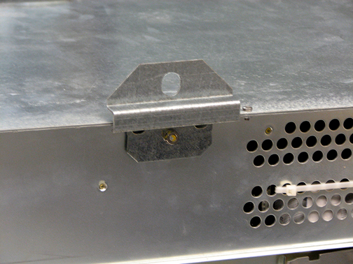
- Attach lifting brackets to each side of the driver module.
Figure 4. Attach Lifting Brackets
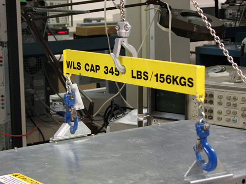
- Attach the lifting bar (hoist kit) to the lifting brackets.
Attach the lifting bar to the hoist chain.
Figure 5. Lifting Bar - Hoist Kit
- Ratchet the winch to tighten the hoist chain.
- Press in the release tabs on each side of the driver module,
and pull it out further from the cabinet.
Figure 6. Slide Rails, Release Tabs
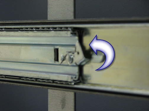
- From the magnet room side, unlatch the locking lever on each
rail to remove the driver module from the PEN cabinet slide rails.
Figure 7. Locking Lever
- Release the PEN cabinet slide rails and slide them back into the cabinet.
- Remove both slide rails from the driver module. See Figure 6.
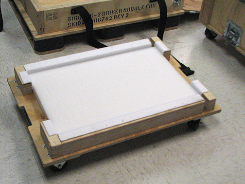
- Lower the driver module onto the FRU packaging platform for
removal.
Figure 8. FRU Packaging Platform
 |
Installing Driver Module
Procedure
- Attach both slide rails to the new driver module. See Figure 6.
- Attach both lifting brackets to the new driver module. See Figure 4.
- Attach the lifting bar (hoist kit) to the lifting brackets; attach the lifting bar to the hoist chain. See Figure 5.
- Ratchet the winch to tighten the hoist chain and begin lifting the module.
- Slide out the PEN cabinet slide rails a short distance to see
how high to lift the module.note:
The slide rails for both the driver module and PEN cabinet must be aligned for proper insertion.
- Finish pulling out each PEN cabinet slide rail until each rail locks into position.
- Carefully slide the driver module slide rails into the PEN cabinet slide rails until they lock into position.
- Loosen the chain tension with the winch.
- Remove the lifting bar from the lifting brackets.
- Remove the lifting brackets from the driver module.
- From the magnet room side, unlatch the locking lever on each rail. See Figure 7.
- Finish pushing the driver module into the PEN cabinet.
- Tighten the four screws to secure the driver module to the PEN cabinet frame. See Figure 1.
- Attach the cables to the rear of the driver module. See Figure 3.
- Tighten the 16 thumb screws to secure the penetration panel to the magnet room wall. See Figure 2.
Finalization
Procedure
- Remove LOTO. See the MR Service Safety Manual, PN 5452735.
- Perform TR Dynamic Disable Calibration.
- Complete a head and body test scan to ensure the system is functional.