- id_12374422
- Version: 1.2
- Date: Jul 5, 2019 10:03:33 PM
Scan Room Power Supply Troubleshooting
This procedure describes how to troubleshoot issues with the Scan Room Power Supply (SRPS), GE P/N 5231801. See Table 1.
 |
|
| Symptom | Cause | Solution |
| All 3 green phase indicators are Off on the Front Panel. See Figure 1. Both green and yellow LEDs are Off on the Phase Relay. See Figure 2. |
|
|
| All 3 green phase indicators are Off on the Front Panel. See Figure 1. Green LED is On and yellow LED is Off on the Phase Relay. See Figure 2. |
Power input phases are swapped (not sequenced properly with respect to SRPS). | Swap input phases at the PEN Cabinet, one at a time until both green and yellow LEDs on Phase Relay are On. |
|
SRPS is not powered, but all LEDs are On (both Phase Relay LEDs and 3 green phase indicators on Front Panel). See Figure 1 and Figure 2. |
|
A confidence loop exists in all SRPS output power cables that,
if opened, will set the SRPS power supply outputs to zero volts.
|
See the following illustrations for location of LEDs and Phase Relay.
Figure 1. Location of Three Green Indicators
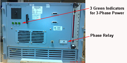
Figure 2. Location of Green and Yellow LEDs and Control Board
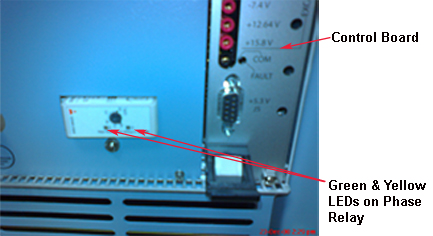
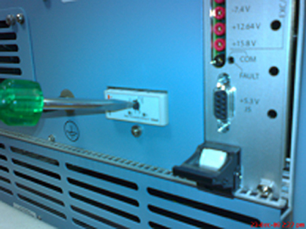
Figure 3. Setting for 160 V