- id_12373650
- Version: 1.2
- Date: Jul 5, 2019 6:08:29 PM
In-Room Display (IRD) Troubleshooting
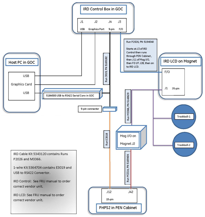
IRD monitor video is supplied by the host PC to a DVI-D connection on an IRDC module inside the GOC. The IRD controller module, also called the IRD fiber optic converter, converts the video to a fiber optic light signal and then sends it over the dual fiber optic cable to be displayed on the IRD monitor display.
Inside the magnet room, data from the operator control panel (enclosure trackball) is routed by USB to the IRD monitor where it is converted to fiber light signals and sent over the dual fiber optic cable to the IRDC module. The IRDC module converts the trackball signals and sends them to the USB connection on the host PC.
1-wire diagnostic information from the IRD monitor and trackballs (which includes trackball USB cable detect, IRD monitor power “good” detect, and dual fiber cable signal “good” detect) is communicated on the copper power cable connection between the IRD monitor J1 and PHPS J42. The PC host receives this information from the USB/serial converter inside the GOC that supports 1-wire network communication from the PHPS. Using this alternate communication path permits IRD hardware status information to still be received by the host PC even if the dual fiber optic cable communication is interrupted because the fiber optic cable is disconnected or connected backwards (that is, normal connection is Tx-Rx or light into dark).
Figure 1. IRD Block Diagram
IRD controller modules are supplied by two vendors: Barco and USEI. The modules look identical. The same keypads function with either module. During operation, cables are connected to J5 and J4. Both are for 1-wire communication. J5 is the sensor input, and J4 is the output to the host PC and PHPS2.
The IRD controller module has several LEDs that provide status information, and can be used for troubleshooting.
Figure 2. IRD Controller LEDs
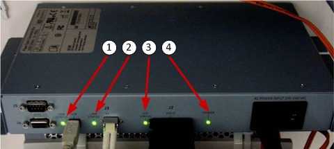
| 1 | USB Status LED | This LED has 2 states: green and dark. Green indicates proper USB communication between IRD module and IRD monitor over dual fiber optic link. This LED does not indicate the condition of USB communication between the IRD monitor and trackball assemblies, or the host PC and IRD module. |
| 2 | Link Status LED | This LED has 3 states: steady green, pulsating green (USEI unit only), and dark (Barco unit only). Steady green indicates proper communication between the IRD module and IRD monitor over dual fiber optic cable. Dark LED (Barco IRD module) or pulsating green LED (USEI IRD module) indicates a failure. |
| 3 | DVI Status LED | This LED has 3 states: green, red, and dark. Green LED indicates that the video cable is attached between the host PC and IRD module and video is present from the host PC. Red LED indicates the video cable is attached between the host PC and IRD module, but video is not active from the host PC. Dark LED and green Power LED indicates that the video cable is not connected between the host PC and IRD module. |
| 4 | Power LED | This LED has two states: green and dark. Green LED indicates that AC power is present at the IRD module. |
The IRD troubleshooting matrix below presents IRD controller LED statuses and possible problems, as well as troubleshooting actions.
Some troubleshooting actions refer to information in In-Room Display Diagnostics.
| IRD Module LEDs | Problem | Actions | |||
| USB Status | Link Status | DVI Status | Power | ||
| Green | Steady green | Green | Green | No video on IRD monitor. |
|
| Green | Steady green | Green | Green | Cannot control cursor on IRD monitor. | A single failed operator control panel (OCP) can disable operation for both sides. OCP trackball assemblies are right and left side specific. Order OCPs for both sides. Install the right side OCP, and check operation. If the problem continues, reinstall the old unit in the right enclosure, install the new left side OCP, and check operation. Return the unused OCP. |
| Green | Steady green | Green | Green | IRD monitor makes loud humming noise. |
|
| Green | Steady green | Green | Green | IRD monitor video too large for display area. |
|
| Green | Steady green | Green | Green | IRD monitor is displaying video meant for host PC monitor. | The monitor video cables are connected to the wrong DVI‐D connectors at the rear of the host PC. Swap the monitor cable connections. |
| Green | Steady green | Dark | Green | Host PC DVI video cable is not attached to IRD module. |
|
| Green | Steady green | Red or orange | Green | Host PC DVI video cable is attached, but video is not present at IRD module from host PC. |
Video is missing if the Host PC did not detect the IRD module, monitor, or trackballs during software boot. Or, video is missing if the IRD software was never installed during installation or after reload.
|
| Dark | Dark | Dark | Dark | IRD hardware power failure. |
|
| Dark | Steady green | N/A | Green | USB communication from IRD module to IRD monitor failed. |
|
| Dark | Blinking green | N/A | Green | Communication is broken between USEI IRD module and USEI IRD monitor on dual fiber optic cable. |
|
| Dark | Dark | N/A | Green | Communication is broken between Barco IRD module and Barco IRD monitor on dual fiber optic cable. |
|