- id_12373872
- Version: 1.4
- Date: Jan 21, 2020 6:38:15 PM
eSRPS Troubleshooting
eSRPS Theory of Operation
The eco-Scan Room Power Supply (eSRPS) is located inside the 1.5T and 3T Penetration Cabinets and supports both 16 and 32 channel systems. See Figure 1 for map of eSRPS power distribution.
Figure 1. eSRPS Power Distribution
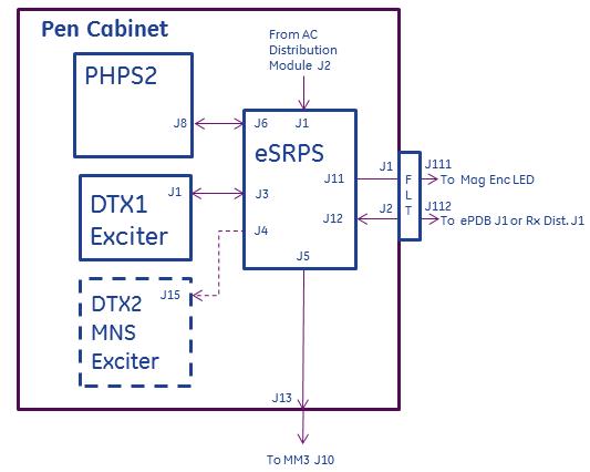
The eSRPS receives 3-phase AC power at J1 from the AC Distribution module located in the bottom of the Penetration Cabinet. It converts the AC voltage to provide DC voltages to these components:
-
Systems with RF Hub, ePDB: +22V
-
Systems with DPP, Rx Distribution Module: +22V
-
DTX1 NB Exciter: +15.8V, +12.64V, +/-7.4V, 5.3V
-
Optional DTX2 BB Exciter: +15.8V, +12.64V, +/-7.4V, +5.3V
-
Magnet Monitor: +5.3V
-
Enclosure LED power supply: +22V
-
PHPS2: 1-Wire communication only; not a power connection.
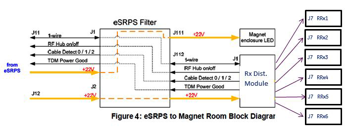
See block diagram of eSRPS in Figure 2. See Figure 3 for diagram showing power connections for systems with RF Hub. In this configuration power from eSRPS J11 & J12 passes through eSRPS Filter located on the Penetration Panel, to ePDB located in the RF Hub, and TDM located on the left side of the magnet. See Figure 4 for systems with DPP receive hardware. In this configuration power from eSRPS J11 & J12 passes through eSRPS Filter located on the Penetration Panel, to Rx Distribution Module located on the left side of the magnet.
Figure 2. eSRPS Block Diagram
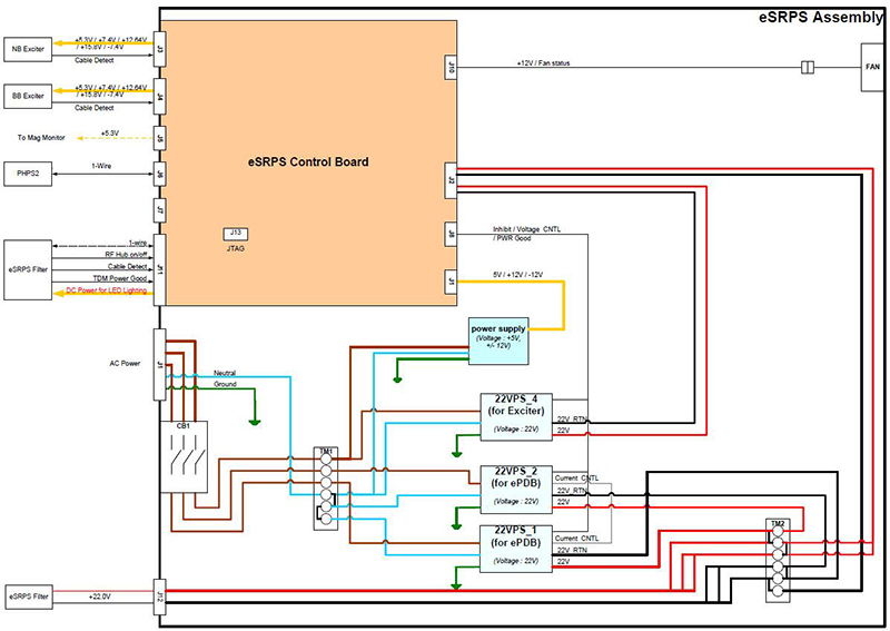
Figure 3. eSRPS Magnet Room Interconnects for System with RF Hub
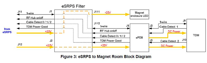
Figure 4. eSRPS Magnet Room Interconnects for System with DPP
Failures internal to eSRPS are reported on the 1-Wire Network (see 1-Wire Network Troubleshooting for Discovery & Optima for example reports). Depending on the severity of the fault, faulted power supplies internal to the eSRPS can be reset by the Host PC from the 1-Wire Network. Status of the eSRPS is indicated visually from 7 green status LEDs on the front of the eSRPS
-
eSRPS POWER (DS LED 1)
-
EXCITER POWER (DS LED 2)
-
MNS EXCITER POWER (DS LED 3; used only if MNS DTX2 installed)
-
RF HUB POWER (DS LED 4; indicates Rx Distribution Module in systems with DPP)
-
RF HUB CABLE (DS LED 5; indicates cable to Rx Distribution Module J1 in systems with DPP)
-
TDM CABLE (DS LED 6; indicates Rx Distribution Module in systems with DPP)
-
TDM POWER GOOD (DS LED 7; indicates Rx Distribution Module in systems with DPP)
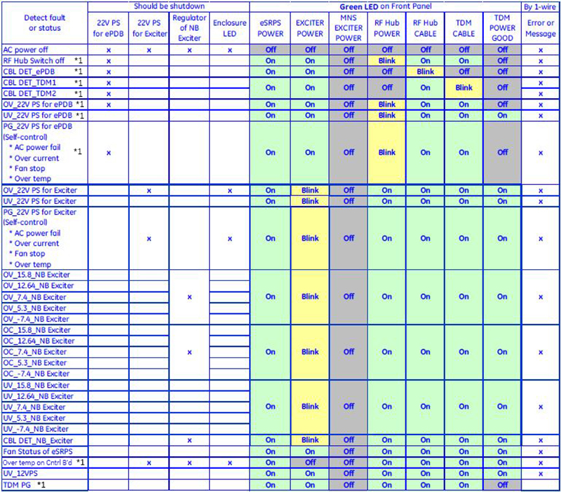
In normal operation these LEDs (with possible exception of MNS EXCITER POWER) are lit. In failure condition one or more of these LEDs are flashing or not lit. Figure 6 and Figure 7 permit correlating visual LED status with fault resulting in shutdown (loss of power) to one or more supported devices.
Systems with RF Hub – ePDB Theory
The eco-Power Distribution Board (ePDB) is located in slot 12 of the RF Hub and is only compatible with the eSRPS. eSRPS supplies ePDB with a single incoming voltage of 22V from which it generates and distributes other voltages to these components:
-
RFSB1, 2 receive +5V_RFSB, +6V_RFSB, +5V_dig_RFSB, -5V_ref.
-
RFCB receives +15V_RFCB, -15V_RFCB, +10V_RFCB, -10V_RFCB, +5V_dig_RFCB, -5V_ref.
-
MCDB1,2 receive +10V_MCDB1, +10V_MCDB2, -10V_MCDB1, -10V_MCDB2, +7V_MCDB1, +7V_MCDB2, -7V_MCDB1, -7V¬_MCDB2, +5V_dig_MCDB, -5V_ref.
-
TDM & RRx1,2 receive +6.85V_TDM, -6.85V_TDM, +6.85V_dig_TDM, +3.16V_dig_TDM, +5.05V_TDM, +5.05V_dig_TDM.
-
RF Hub Backplane & RRx1,2 receive +3.3V_dig_BKPL_RRx.
See Figure 5. ePDB uses switching regulators to generate the distributed voltages, unlike PDB and PDBv which use linear regulators. Due to the use of switching regulators no sense wires for voltage drop compensation exist between eSRPS and ePDB or ePDB and TDM.
Figure 5. ePDB Block Diagram
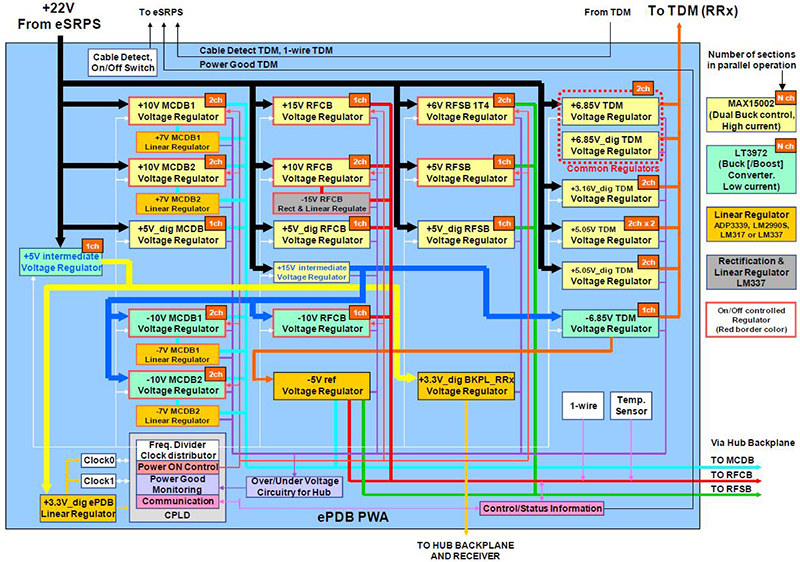
A front panel POWER rocker switch located on the front of the ePDB is normally in “I (ON)” position. In this position it completes the loop for the RF Hub On/Off +12V signal that originated in the eSRPS, permitting the eSRPS to output power to the ePDB. In the “O (OFF)” position this switch opens the loop, interrupting the RF Hub On/Off signal, resulting in the eSRPS removing power from the ePDB. The ePDB must be installed in slot 12 of the RF Hub to receive power from the eSPRS as the RF Hub On/Off signal path is through a set of loopback connectors in the RF Hub backplane.
4 status LEDs are visible from the front panel of the ePDB:
-
FREQ_1 This and FREQ_2 LED indicate field strength, nuclei selected. When only this LED lit ePDB operating in 3T mode. Other illumination combinations (dark, flashing) for 3T MNS.
-
FREQ_2 This and FREQ_1 LED indicate field strength, nuclei selected. When only this LED lit ePDB operating in 1.5T mode. Other illumination combinations (flashing) for 3T MNS.
-
ANALOG_PW RFCB can disable/enable ePDB RFCB voltage regulators. Lit when these enabled.
-
22V_IN Lit when +22V from eSRPS present.
4 POWER GOOD status LEDs are visible from the front panel of the ePDB:
-
TDM Lit when the following voltages are normal: +6.85V_TDM, -6.85V_TDM, +5.05V_TDM, +5.05V_dig_TDM, +3.16V_dig_TDM.
-
HUB ANALOG Lit when the following voltages are normal: +15V_RFCB, -15V_RFCB, +10V_RFCB, -10V_RFCB, +10V_MCDB1, +10V_MCDB2, -10V_MCDB1, -10V_MCDB2, +6V_RFSB, +5V_RFSB, -5V_ref.
-
HUB DIG Llit when the following voltages are normal: +5V_dig_RFCB, +5V_dig_MCDB, +5V_dig_RFSB, +3.3V_dig_BKPL_RRx.
-
PDB INT Lit when the following voltages internal to ePDB are normal: +15V_intermediate, +5V_intermediate, +3.3V_dig_ePDB.
Systems with DPP – Rx Distribution Module Theory
Systems with DPP do not have an RF Hub or ePDB. Power from eSRPS is delivered as a single incoming voltage of 22V directly to Rx Distribution Module J1 located on the left side of the magnet. Other voltages are generated inside the Rx Distribution Module from the 22V and shared directly with the 32-channel RRx modules. The Rx Distribution Module is only compatible with the eSRPS. See Figure 4. The “Analog Power Good” LED on the top of the Rx Distribution Module is green to indicate that incoming 22V power is OK.
Troubleshooting
Remove power from eSRPS before removing or connecting any cables.
-
Be aware that problems with eSRPS, especially during installations and upgrades, are most often due to poor, missing, or swapped cable connections. Remove, check cable label, and reconnect all cable connections, starting at front of eSRPS, ePDB and TDM or Rx Distribution Module.
-
Install the Advanced or Restricted service key and review error messages and corresponding proprietary extended error messages from the Error Log viewer located in the Common Service Desktop.
-
Error log references to multiple components usually indicate failure of something common to components.
-
References to single RF Hub component may mean that component faulty (systems with DPP refer to Rx Distribution Module).
-
-
Review state of DS LEDs 1 – 7 on front of eSRPS.
-
Sites with MNS option: Normally all LEDs on; compare LED states to those listed in Figure 6.
-
Sites without MNS option: Normally LED 3, MNS EXCITER off; compare LED states to those listed in Figure 7.
-
Figure 6 and Figure 7 acronyms defined: BB – BroadBand (also known as Multi-Nuclear Spectroscopy), CBL – cable, DET – Detect, NB – Narrow Band, OV – Overvoltage, PG – Power Good, PS – Power Supply, UV – Undervoltage.
-
- If the system is reporting an eSRPS 22V power supply fault:
- Check the incoming 208VAC power phases and the neutral at eSRPS J1.
- Check that the load connected at eSRPS Filter J111 in not short-circuited.
- Continue to the next step and troubleshoot.
-
Systems with RF Hub: See Figure 6, Figure 7 and Table 1 review status LEDs on front of ePDB and compare to states described in ePDB Theory section.
-
Systems with DPP: See Table 5 and review status LEDs on Rx Distribution Module.
-
If message log reports overcurrent failure at TDM or Rx Distribution Module, disconnect grey cable between the failing RRx and TDM or Rx Distribution module and DPP RRX to see if reported message changes. Disconnecting cables at RF Hub ePDB J2 or J3 is not permitted and will result in disabling of power from ePDB.
-
If necessary perform 1-Wire Network Diagnostic and review results and Error Message contents to diagnose to bad cable connection or component. See Table 1 for example of normal 1-Wire Network Diagnostic results. If system has a RF Hub, 1-Wire results OK, but RRx missing power, check for swapped J2 and J3 at ePDB or J9 and J10 at TDM.
*1 — On systems with DPP, this applies to power cable to Rx Distribution Module or Rx Distribution Model.
Figure 6. eSRPS LED states for sites with MNS (BB)
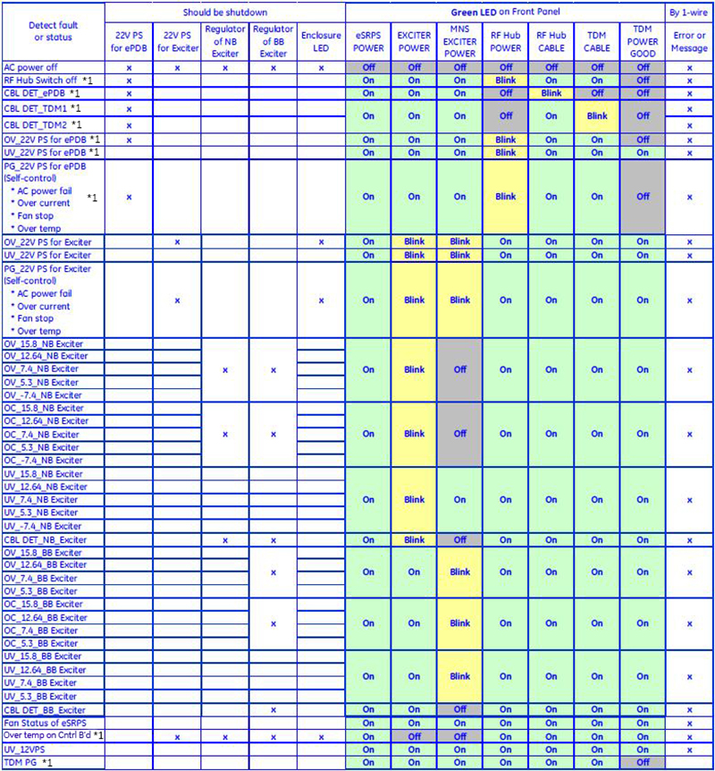
*1 — On systems with DPP, this applies to power cable to Rx Distribution Module or Rx Distribution Model.
Figure 7. eSRPS LED states for sites without MNS
| NOTES | |
| TDM Board ID Detected | Only valid for systems with RF Hub |
| TDM I/O Detected | Only valid for systems with RF Hub |
| SRPS TDM Input Power OK | Only valid for systems with RF Hub |
| SRPS TDM Internal 3.3V Power OK | Only valid for systems with RF Hub |
| SRPS TDM Clock Input Present | Only valid for systems with RF Hub |
| SRPS TDM Clock Output Present | Only valid for systems with RF Hub |
| SRPS TDM Loop Antenna Present | Only valid for systems with RF Hub |
| TDM RRx I/O Detected | Only valid for systems with RF Hub |
| RRx 1 Present | Only valid for systems with RF Hub |
| RRx 2 Present | 32ch systems only; valid for systems with RF Hub |
| eSRPS Ctrl Board ID Detected | |
| eSRPS Exc I/O Detected | |
| eSRPS Exciter Over Voltage OK | |
| eSRPS Exciter Under Voltage OK | |
| eSRPS Exciter Over Current OK | |
| eSRPS MNS Exciter Over Voltage OK | Only present if MNS installed |
| eSRPS MNS Exciter Under Voltage OK | Only present if MNS installed |
| eSRPS MNS Exciter Over Current OK | Only present if MNS installed |
| eSRPS Ctrl Board I/O Detected | |
| RF Hub/TDM Power is On | Only valid for systems with RF Hub |
| eSRPS AC Input Status OK | |
| eSRPS 12V Voltage OK | |
| eSRPS Control Board Over Temperature OK | |
| eSRPS Control Board Fan OK | |
| eSRPS Power Supply I/O Detected | |
| eSRPS Exciter 22V Over Voltage OK | |
| eSRPS Exciter 22V Under Voltage OK | |
| eSRPS Exciter 22V Power Supply OK | |
| eSRPS RF Hub 22V Over Voltage OK | |
| eSRPS RF Hub 22V Under Voltage OK | |
| eSRPS RF Hub 22V Power Supply OK | |
| eSRPS Cable Detect I/O Detected | |
| eSRPS TDM Cable1 Detected | Only valid for systems with RF Hub |
| eSRPS TDM Cable2 Detected | Only valid for systems with RF Hub |
| eSRPS Exciter Cables Detected | |
| eSRPS MNS Exciter Cable Detected | Only present if MNS installed |
| eSRPS ePDB Cable Detected | Only valid for systems with RF Hub |
| Front Status LEDs | Status | LED Description |
| +5D |
Green – OK Red – fault |
Power good status for voltage supplied by ePDB. |
| -5V | ||
| +5V | ||
| +6V |
| PWR GOOD LEDs | Status | LED Description |
| +5V | Green - OK | Power good status for voltage supplied by ePDB. |
| -5V | ||
| -7V | ||
| +7V | ||
| +10V | ||
| -10V | ||
| +3.3V | Power good status for voltage from onboard regulator. | |
| +1.2V | Power good status for voltage from onboard regulator. |
| Front Status LEDs | Status | LED Description |
| +5V | Green - OK | Power good status for voltage supplied by ePDB. |
| +3.3V | Power good status for voltage from onboard regulator. | |
| +1.2V | Power good status for voltage from onboard regulator. | |
| +10V | Power good status for voltage supplied by ePDB. | |
| -10V | ||
| +15V | ||
| -15V |
| Front Status LEDs | Status | LED Description |
| Analog PWR Good | Green - OK | Incoming 22V from eSRPS OK. |
| FPGA PWR Good | Internal mainboard power OK. |