- id_12374689
- Version: 1.6
- Date: Jul 5, 2019 6:08:29 PM
Test T/R Pin Diode for Noise (Head or Body)
Prerequisites
| Required persons | Preliminary requirements | Procedure | Finalization |
|---|---|---|---|
| 1 | Not Applicable | 15 minutes | 20 minutes |
Overview
The Pin Diode Test identifies if the T/R Diode is creating excess noise. It takes two noise scans with and without T/R enabled. This procedure will not assist in diagnosing T/R faults.
Procedure
- Start a new study.
- Select either the Head or Body Coil.
- If testing the head coil, place it on the cradle, landmark on the coil, and advance to scan.
- If testing the body coil, landmark on a valid cradle position and advance to scan. Do not install or use a phantom.
- Set up to scan using the following protocol:
- Axial
- 2D
- GRE
- TE: 34 (OK to use a different value to please scanner)
- TR: 20 (OK to use a different value to please scanner)
- Flip angle: 10 (OK to use a different value to please scanner)
- Bandwidth: 15.63 (15 to16 KHz OK)
- FOV: 24
- Slice thickness: 10 mm
- Space: 1.5 mm (OK to use a different value to please scanner)
- Start: 0
- Stop: 0
- Yres: 256
- Xres: 256
- NEX: 1
- Download series.
- Click arrow next to the SCAN option, select Research, then Display CVs.
- Modify CV “rawmode”, setting the value to 1, then select Accept.
- Click the arrow next to Scan button and select Research Options and select Download.
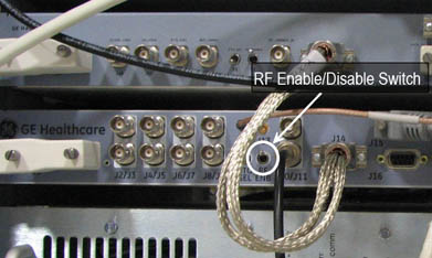
- Disable Exciter RF Output by moving the RF ENB switch to the
down position. See Figure 1.
Figure 1. Exciter RF ENB Switch
- note:Enter manual prescan and set R1 and R2 to max, and TG to 0, then exit manual prescan.
The RF ENB switch on the Exciter RF has to be up to Enable RF Output and pushed down to Disable RF Output.
- Scan and record Study/Series/Image numbers in A column. See Table 2.
- Remove TR input going to RF power amplifier.
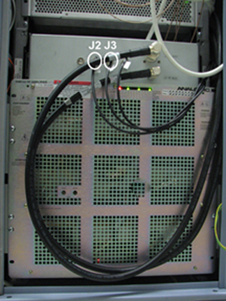
- Remove J3 on RF Amplifier for Head mode.
- Remove J2 on RF Amplifier for Body mode.
- Remove J13 RF In cable from RF amplifier.
Figure 2. J2 and J3 on SRFD Amplifier
- Turn the TR fault detection switch, on the driver module, to the disable position (down).
- Scan and record Study/Series/Image numbers in the B column. See Table 2.
- Display the first image from Step 10 and verify there is no coherent noise seen (patterns such as solid or dashed lines, or pattern of dots). Record if coherent noise exists in the A column. See Table 2.
- Place an ROI (Region Of Interest) centered on the image and covers 60 to 80 percent of the image.
- Record the mean and standard deviation in the A column. See Table 2.
- Display the first image from Step 13 and verify there is no coherent noise seen (patterns such as solid or dashed lines, or pattern of dots). Record if coherent noise exists in the B column. See Table 2.
- Place an ROI (Region Of Interest) centered on the image and covers 60 to 80 percent of the image.
- Record the mean and standard deviation in the B column. See Table 2.
Table 2 Data Entry and Analysis A B Study Series Image Mean Standard Deviation (STD) Coherent noise exists? Yes/No - Analyze the results from Table 2:
-
If coherent noise exists, then the Pin Diode Test is invalid, and this indicates a problem. See Table 3 for potential coherent noise issues.
-
If coherent noise does not exist, perform the following calculation: C=100*(STD_A-STD_B)/STD_A
-
If C is less than ±1.5%, Pin Diodes may be faulty.
Table 3 Potential Causes of Defective Pin Diodes Possible Causes Coherent Noise only on A Noise from TR driver getting through bias T in RF power amplifier Coherent Noise only on B TR diodes turning on/off by noise Coherent Noise on both Noise received from coil from noise in magnet room, or generated by the coil or TR electronics -
Finalization
- Reconnect any cables that you removed during this procedure.
- Place Driver Module TR fault detection switch in Enabled (up) position.
- Place RF ENB Switch on Exciter in Enabled (up) position.