- id_12374185
- Version: 1.3
- Date: Jul 5, 2019 10:03:32 PM
Exciter (with Electric Clock) Troubleshooting
The front panel LED indicators identify the state of the components and connections for the exciter with electric clock. Some indicators are associated with a 1-wire status as shown in Table 1.
In addition to the 1-wire network diagnostics, the functional unblanking diagnostic in the service browser can be used to troubleshoot suspected loss of unblank signals in the exciter. See Functional Unblanking Diagnostic for instructions to run this diagnostic.
Figure 1. Exciter Front Panel LEDs
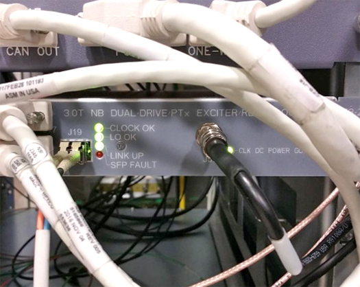
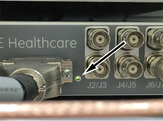
Figure 2. Exciter Power Good LED (Unlabeled, Located by J1)
| Indicator | Status | Description | 1-Wire Status (NB Exc, NB Exc I/O Board, or Clk Ref Board) | Suggested Service Actions |
| CLOCK OK | Green | The 80 MHz system clock signal is being generated on the clock reference board and received by the exciter board. | Exciter 80MHz Clock OK Exciter Clock Ref 80MHz Detected |
None |
| Off | The clock is not being generated on the clock ref board or the exciter board is not receiving the clock signal properly. | Exciter 80MHz Clock Not OK Exciter Clock Ref 80MHz Not Detected |
Confirm/reseat all clock connections from the exciter module. If ICE and/or the Receive chain also report a missing clock signal, and the connections are OK, the clock source on the clock ref board has failied. Replace the exciter module. If only the exciter board is reporting a missing clock signal, then an internal harness has failed. Replace the exciter module. |
|
| LO OK | Green | The LO signal is present and operational. This signal is generated in the clock reference board inside the exciter module and detected at the exciter board. | Exciter LO OK | None |
| Off | The LO signal is not available to the exciter board inside the exciter module or the LO source on the clock reference board is not functional. | Exciter LO Not OK | Confirm/reseat all LO connections from the exciter to the receive
chain. If the Receive chain also reports a missing LO signal, and the connections are OK, the LO source on the clock ref board has failied. Replace the exciter module. If only the exciter board is reporting a missing LO signal, then an internal harness has failed. Replace the exciter module. |
|
| LINK UP | Green | The incoming DVLink to the exciter is connected and operational. | Exciter Fiber Optic Signal Presence Exciter FPGA Up Exciter Fiber Optic Link Up |
None |
| Off | the DVLink is not connected to the exciter, the sequencer is not transmitting properly or the exciter is not responding properly. | Exciter Fiber Optic Signal Loss Exciter FPGA Down Exciter Fiber Optic Link Down |
Check the DV link connection to the exciter module TPS reset. Run the DVMR Link Status diagnostics to determine if the issue is on the sequencer side or the exciter side. Try moving the DV link connection for the exciter to a different sequencer port on ICE/CAM. |
|
| SFP FAULT | Red | The SFP module is missing, not fully seated, or is not transmitting data from the exciter properly. | Exciter SFP Tx Not OK | Confirm the SFP module is installed properly at the exciter
module. Swap the SFP module from the exciter with an unused module from the ICE (if available). Replace the SFP module. |
| Off | The SFP is working properly. | Exciter SFP Tx OK | None | |
| CLK DC POWER GOOD | Green | The clock reference board is powered up. | Exciter Clk Ref Power Status OK | None |
| Off | The clock reference board is not receiving DC power from the exciter board. | Exciter Clk Ref Power Status Not OK | Confirm connection to exciter module J1 is seated properly. Confirm Exciter DCPS or eSRPS is powered up properly and that voltages are present on the connection into the exciter. If incoming power is OK, an internal circuit or harness has failed. Replace the exciter module. |
|
| EXCITER POWER GOOD (small LED next to J1 on front panel, not labeled) | Green | Exciter board incoming power and all regulators are working properly. | Exciter Digital Power OK Exciter Power OK |
None |
| Off | One or more voltage rails on the exciter board is low or missing. | Exciter Digital Power Not OK Exciter Power Not OK |
Confirm connection to exciter module J1 is seated properly. Confirm Exciter DCPS or eSRPS is powered up properly and that voltages are present on the connection into the exciter. If incoming power is OK, an internal circuit or harness has failed. Replace the exciter module. |