- id_12373438
- Version: 1.1
- Date: Jul 5, 2019 10:03:32 PM
CPC MNS Amplifier (5750811) Troubleshooting
Procedure Overview
 |
|

The Bird RF power measurement kit (Part# 5307511-3) is used for troubleshooting.
Use this document to troubleshoot CPC hardware failures. To troubleshoot MNS problems not specific to the CPC hardware, see MNS Troubleshooting
This document contains sections as follows:
-
Amplifier Diagnostics describes CPC status LEDs and provides a simple RF block diagram
-
Reference Documents/Vendor Manuals lists reference documents
-
CPC Fault LED/Solution Table contains a CPC Fault LED/Solution table, a Troubleshooting by Symptom table, and an interface connector pin-out list
-
7 System States and Conditions describes various CPC system states and descriptions of various fault conditions
-
Troubleshooting for Low Gain describes the process for locating the RF component failing with low gain
Amplifier Diagnostics
The Status LED on the driver chassis of the CPC amplifier shows the system status of the CPC amplifier. There are also power LEDs and fault LEDs on the 2 modules.
Figure 1. CPC RF Amplifier: 3T8000MG-2 Rack Layout (Front View)
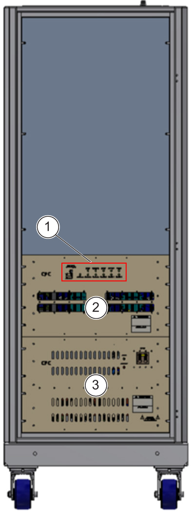
| ITEM | DESCRIPTION |
| 1 | LED status |
| 2 | CPC power module |
| 3 | CPC power supply |
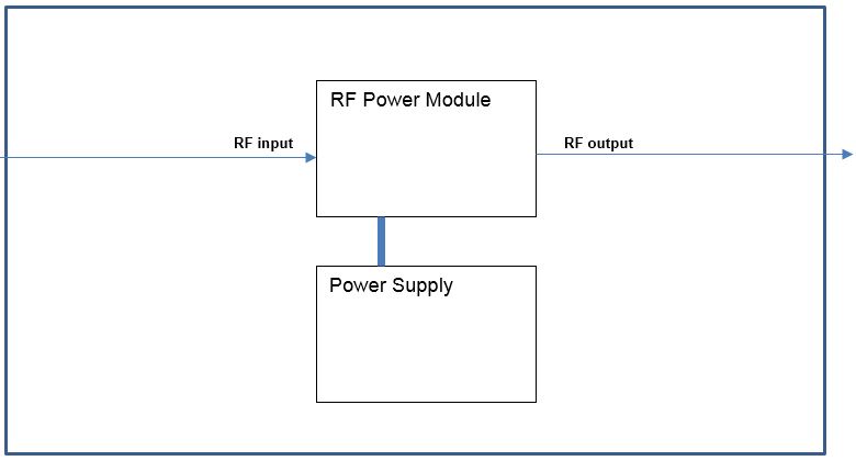
Figure 2. CPC RF Amplifier Basic Block Diagram
Reference Documents/Vendor Manuals
See these documents for additional information:
-
Operating Manual for CPC Model # 3T8000MG-2 RF Power Amplifier System (available from the online documentation library by searching for document 3T8000MG-2)
-
FRU manual, see Service Methods FRU list for MR750w or MR750 for list of FRUs
CPC Fault LED/Solution Table
In many cases, problems with the CPC amplifier are displayed through fault codes. Six status code LED indicators, labeled left-to-right 5 to 0, are on the front of the cabinet. These indicators display status and fault codes.
When the amplifier is turned on, or the AC power is cycled, the system goes through a warm-up period of approximately five minutes. If a fault happens during the warm-up period, the amplifier is forced into a Standby condition and cannot be enabled or unblanked from the MR system. In this condition, a fault message will not be reported to the MR system, but a fault condition will be displayed on the CPC fault status LEDs. You must cycle AC power to the CPC in order to reset it from the Standby condition, and restart the five minute warm-up period.
Table 1shows fault codes, a description of each fault, the recommended action and, if applicable, necessary replacement parts to overcome the fault that can be seen via the fault code LEDs.
Table 2 shows a list of problems, probable causes and solution recommendations.
| Status Code seen at LEDs and J1 5 MSB, 0 LSB | Status Code in HEX | Operational LEDs | Description | ||||
| POWER | STANDBY | READY | UNBLANK | FAULT | |||
| 000000 | Hex 00 | off | off | off | off | off | No power to amplifier or interface disconnected. |
| 000001 | Hex 01 | ON | off | ON | off | off | Operational state. Ready for RF. Warm-up time has expired, ENABLE is active, and no UNBLANK command from either J1 or J2. |
| 000001 | Hex 01 | ON | off | ON | ON | off | Operational state with UNBLANK command from either J1 or J2. |
| 000010 | Hex 02 | ON | ON | off | off | off | Transient state, in warm-up. UNBLANK commands from J1 and J2 have no effect. |
| 000011 | Hex 03 | ON | ON | ON | off | off | Standby, ENABLE not active, and warm-up has expired. UNBLANK commands from J1 and J2 have no effect. |
| 000100 ≡ 100000 | Hex 04 ≡ Hex 20 | – | – | – | – | – | Not used. |
| 100001 | Hex 21 | ON | ON | ON | off | ON | Power supply fault. |
| 100010 ≡ 100111 | Hex 22 ≡ Hex 27 | – | – | – | – | – | Not used. |
| 101000 | Hex 28 | ON | ON | ON | off | ON | Overdrive Fault |
| 101001 | Hex 29 | ON | ON | ON | off | ON | Thermal Fault. |
| 101010 | Hex 2A | ON | ON | ON | off | ON | Peak Power Fault |
| 101011 | Hex 2B | ON | ON | ON | off | ON | Energy (average power) Fault |
| 101100 | Hex 2C | ON | ON | ON | off | ON | VSWR Fault |
| 101101 | Hex 2D | ON | ON | ON | off | ON | Pulse Width Fault. |
| 101110 | Hex 2E | ON | ON | ON | off | ON | Duty Cycle Fault |
| 101111≡ 110110 | Hex 2F ≡ Hex 36 | – | – | – | – | – | Not used. |
| 110111 | Hex 37 | – | – | – | – | – | Not used. |
| 111000 | Hex 38 | ON | ON | ON | off | ON | Under voltage fault |
| 111001 | Hex 39 | ON | ON | ON | off | ON | Over voltage fault |
| 101011≡ 111111 | Hex 3B ≡ Hex 3F | – | – | – | – | – | Not used. |
| Symptom | Probable Cause | Recommendations |
| Thermal fault status code |
|
|
| No air flow |
|
|
| Overdrive fault status code | Excessive RF input level | Reduce RF input level |
| High load VSWR fault status code | Excessive output VSWR | Check cables, tuning probe, or load |
| Pulse width fault status code |
|
|
| Duty cycle fault status code |
|
|
| Low RF gain (high distortion) |
|
|
| No RF output |
|
|
| Power supply fault status code |
|
|
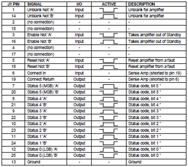
Figure 3. Interface Connector Pin-Out Assignment
7 System States and Conditions
Operate
If the amplifier is enabled through the system interface (J1), it is in Operate mode. In this mode, the amplifier can be unblanked and used normally
Standby
If the amplifier is disabled through the system interface (J1), or the system interface connector is not sensed, the amplifier enters Standby mode. In this mode, the amplifier cannot be unblanked and the internal devices are turned off.
7.3 Fault State
If a fault occurs while the system is in the Ready state, the system enters the Fault state. In this state, the amplifier is forced into Standby mode and the fault condition is indicated. Faults are latched, so the system remains in the Fault state even if the condition which triggered it is no longer present.
Fault Reset: The system will remain in the Fault state until it receives a Fault Reset command from the system interface (J1). When the system is reset from a fault, it will go back to the Ready state if the condition that triggered the fault is no longer present. If the condition is still present, then the amplifier will remain in the Fault state even after a fault reset. The Fault Reset command has no effect outside of the fault state.
Fault Descriptions
| Reflected power (VSWR) fault | Reflected power protection is achieved by monitoring the absolute reflected power levels. A fault is generated when the level exceeds approximately one third of the rated output power of the amplifier. The circuit is disabled upon the first 1 ms of the pulse. Upon fault, the amplifier will shut down and the status code will be updated. |
| Overdrive fault | The overdrive protection circuitry monitors the RF envelope at the output of the amplifier system. The signals are then compared using threshold comparators. If the threshold is reached, the amplifier will shut down and the status code will be updated. |
| Peak Power Fault | The peak power protection circuitry monitors the RF envelope at the output of the amplifier system. The signals are then compared using threshold comparators. If the threshold is reached, the amplifier will shut down and the status code will be updated. |
| Energy fault | The energy protection circuitry monitors the RF envelope at the output of the amplifier system. The circuit contains an integrator that is capable of integrating a variety of pulses at different duty cycles. This integrated signal is then compared using a threshold comparator. If the threshold is reached, the amplifier will shut down and the status code will be updated. |
| Thermal fault | Each heat sink is provided with a bimetallic thermal sensor. In the event of an over-temperature condition, the amplifier will shut down and the status code will be updated. After sufficient time has passed to allow the heat sink to cool, the amplifier can be reset manually as described in the previous section. |
| Power supply fault | The power supply protection circuitry monitors all auxiliary voltages and the main DC voltage supply. In the case of a fault, the amplifier will shut down and the status code will be updated. A second degree of protection is provided at the amplifier module level; see the descriptions for under-voltage fault, over- voltage fault, and over-current fault. |
| Pulse width fault | The amplifier is equipped with envelope detection circuitry that monitors the pulse width of the RF input. The width of this envelope is compared with a pre-set threshold. If this threshold is exceeded, the amplifier will shut down and the status code will be updated. |
| Duty cycle fault | The amplifier is equipped with envelope detection circuitry that monitors the duty cycle of the RF input. The repetition of this envelope is compared with a pre-set threshold. If this threshold is exceeded, the amplifier will shut down and the status code will be updated. |
| Under-voltage fault | If the high current DC voltage in the system drops too low on an RF module, then the amplifier will shut down and the status code will be updated. |
| Over-voltage fault | If the high current DC voltage in the system goes too high on an RF module, then the amplifier will shut down and the status code will be updated. |
| Over-current fault | If an RF module is drawing excessive current, then the amplifier will shut down and the status code will be updated. |
| Interconnect fault | "Interconnect Fault" is an obsolete fault condition that is not present in the 3T8000MG-2 amplifier system. |
Troubleshooting for Low Gain
This version of CPC amp contains only one module that produces the RF Output. The only troubleshooting for this module is to confirm that there is RF output going into the Power Amplifier module using an oscilloscope, and then confirm that there is RF output coming out of the module using the RF power measurement kit.
Finalization
-
Reset any hardware changes to return the system to normal product configuration.
-
If components were swapped during the troubleshooting process, perform MNS Functional Checks.