- Optima MR450w BASE 1.5T System Service Methods
- 5690012-2EN Revision 3
- 00000018WIA30BBE030GYZ
- id_123745925.0
- Dec 4, 2019 12:30:13 AM
Applying LOTO - PGR PDU/Gradient Subsystem
Prerequisites
| Personnel requirements | |||
|---|---|---|---|
| Required persons | Preliminary requirements | Procedure | Finalization |
| 1 | - | 10 minutes | - |
| Tools and test equipment | |||
|---|---|---|---|
| Item | Quantity | Part number | Manufacturer |
| Brass Master Padlock with Brass Shackle | 2 | 46-194427P320 | - |
| Red LOTO Personal Lock Wrap | 2 | 2393068 | - |
| Multi-Locking Device (if multiple service personnel are involved) | 1 | 46-194427P313 | - |
| Red Warning LOTO Tag | 2 | 46-194427P322 | - |
| Digital Voltmeter (DVM) | 1 | 46-194427P284 | - |
About this task
| ||||
Overview
The Power, Gradient, RF Cabinet (PGR) Power Distribution Unit (PDU) and eXtreme Gradient Amplifier (XGA) reside in the PGR cabinet. The XGA is part of the eXtreme Gradient Driver (XGD) subsystem. Prior to servicing and/or maintenance work on the PGR PDU or any element of the XGD, the steps in this Lock Out / Tag Out (LOTO) procedure must be completed by a LOTO-authorized GE Field Engineer (FE). Completing all the steps in this procedure ensures a safe environment and avoids equipment damage when working on these parts.
| Name of Equipment | Number of Locks | Titles of Employees Authorized to perform LOTO | Titles of Affected Employees | How to Notify |
|---|---|---|---|---|
|
2 per GE FE | GE FEs | Hospital personnel | Verbal, posted signs |
| Energy source | Yes | No | Location of energy isolating means | Magnitude of energy |
|---|---|---|---|---|
| Electrical | x | PGR PDU circuit breaker panel, Main Disconnect Panel (MDP) circuit breaker panel | 208 VAC, 420 VAC, 380-480 VAC | |
| Pneumatic | x | |||
| Hydraulic | x | |||
| Gas/Water/Steam | x | |||
| Chemical | x | |||
| Mechanical Motion | x | |||
| Gravity | x | |||
| Springs | x | |||
| Thermal | x | |||
| Stored Energy | x | Time discharge of internal capacitors | 208 VAC, 420 VAC | |
| Air Under Pressure | x | |||
| Oil Under Pressure | x | |||
| Water Under Pressure | x | Heat Exchanger Cabinet (HEC), PGR Pump Circuit Breaker (PPMPCB) and RF amp quick disconnect | 5.0 Bar (80 psi) | |
| Gas Under Pressure | x | |||
| Steam | x | |||
| Other | x |
Types of equipment and/or methods selected to dissipate or isolate stored energy
About this task
Type(s) of equipment and/or method(s) used to ensure disconnection(s)
Procedure
- Two personal locks and tags per FE at the site working on the de-energized equipment at the time of LOTO.
- Voltmeter to read voltage for verification that energy has dissipated in the PDU.
Applying LOTO
Procedure
- At the PGR cabinet, go to the front panel of the PGR PDU and
press the POWER OFF button.
Figure 1. Shut Down PGR PDU Power and LOTO 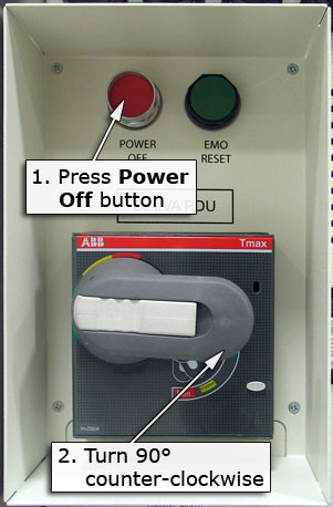
- At the front panel of the PGR PDU, pull out the locking mechanism on the end of the main breaker (or, on the new breaker, press on the arrow) to expose the hole where the lock and tag can be placed.
Put the LOTO lock on the PGR PDU main breaker.
Figure 2. Locking the main breaker 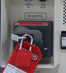
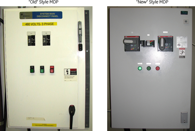
- Locate and turn off the PGR PDU main breaker on the MDP that feeds the PGR cabinet.
Lock Out/Tag Out the PDU breaker on the MDP.
Figure 3. PDU breaker on old style MDP 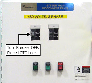
Figure 4. PDU breaker on new style MDP 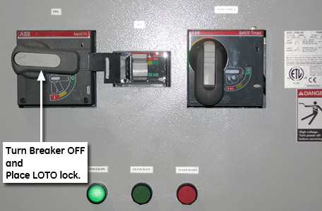
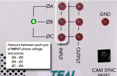
- Make sure all energy has been dissipated. Use a voltmeter to measure the line-to-line voltage between each INPUT phase voltage test point on the PDU.Note: The test points are 100:1 ratio (480 VAC = 4.80 VAC, 208 VAC = 2.08 VAC). Therefore, a low voltage reading still indicates the presence of high voltage. Your voltage reading for each of the three phases must be 0 VAC before proceeding.
Input Voltage Range: 380 - 480 VAC = 3.8 - 4.8 VAC
Output Voltage Range: 208 VAC = 2.08 VAC
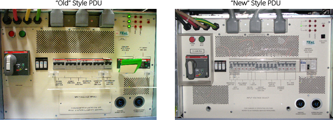
Figure 5. Old style PDU test points 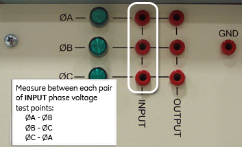
Figure 6. New style PDU test points