high bias voltages are present at the Body Hybrid during normal operation.
Remove power and perform LOTO on the PDM-RF power on pdu before accessing the Body Hybrid. See the “MR Service Safety Manual,” PN 5452735.
CAUTION
Strong Magnetic Field!
The module has no ferrous material and is not attracted to the magnet, but eddy currents set up by the strong magnetic field interacting with the body hybrid module can make it very hard to handle.
When removing and or replacing the body hybrid module from the side of the magnet, keep the module as far away from the magnet as possible.
Removing Body Hybrid Splitter
Procedure
Perform LOTO on the PDM-RF power for the system. See the MR Service Safety Manual, PN 5452735.
Make sure the scanner is idle. Select End Exam at any point in the scan process.
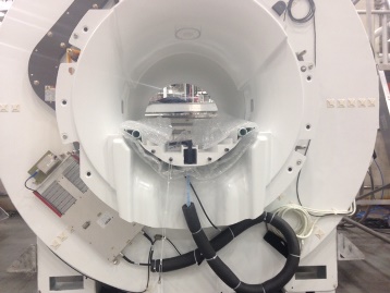
Remove all routed cables connected to the body hybrid module.
Figure 1. Routed Cables
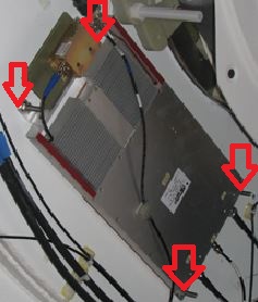
Loosen the 4 nuts that secure the body hybrid module to the magnet.
Remove the 4 brackets from the old module.
Figure 2. Brackets
CAUTION
Strong Magnetic Field!
The module has no ferrous material and is not attracted to the magnet, but eddy currents set up by the strong magnetic field interacting with the body hybrid module can make it very hard to handle.
When removing and or replacing the body hybrid module from the side of the magnet, keep the module as far away from the magnet as possible.
Remove the module from the magnet room, and keep it as far away from the magnet as possible.
Installing Body Hybrid Module
Procedure
CAUTION
Strong Magnetic Field!
The module has no ferrous material and is not attracted to the magnet, but eddy currents set up by the strong magnetic field interacting with the body hybrid module can make it very hard to handle.
When removing and or replacing the body hybrid module from the side of the magnet, keep the module as far away from the magnet as possible.
Move the module into the magnet room, and keep it as far away from the magnet as possible.
Install the brackets from the old module onto the new module.
Secure the module to the magnet by tightening the 4 nuts provided.
Re-attach the routing cables to the new body hybrid module.
Note:
Ensure the RF cables from the hybrid to the body coil remain dressed and routed as shown in Figure 1 after body hybrid replacement.
Replace all covers in reverse order.
Remove LOTO and reapply power to the system. See the latest revision of the MR Service Safety Manual, PN 5452735.