
- Optima MR450w BASE 1.5T System Service Methods
- 5690012-2EN Revision 3
- 00000018WIA30A51E20GYZ
- id_131058563.0
- Aug 29, 2019 1:39:23 AM
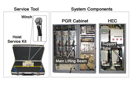
Hoist Service Kit and Lifting Accessories
Prerequisites
| Required persons | Preliminary requirements | Procedure | Finalization |
|---|---|---|---|
| 1 | Not Applicable | Not Applicable | Not Applicable |
| Item | Quantity | Effectivity | Part number | Manufacturer |
|---|---|---|---|---|
| Main Lifting Beam (System Component) | 1 | - | - | - |
| Support Tube (System Component) | 1 | - | - | - |
| Service Platform (System Component) | 1 | - | - | - |
| Hoist Service Kit (Service Tool) | 1 | - |
5196226 | - |
| Non-Magnetic Tool Kit (or equivalent) | 1 | - |
5113258 | - |
| ||||||||
About this task
The hoist service kit and lifting accessories assist in the removal and replacement of Equipment Room FRUs that weigh 36 to 345 pounds (16.3 to 156.5 kg). The hoist consists of a service tool and system components. The winch with chains and spreader bar for lifting the replacement FRUs are in the hoist service kit. The support tube (located in the HEC) and main lifting beam (located in the PGR Cabinet) are system components.
This document reviews the fundamentals of the hoist, discussing proper set up of the hoist service kit and lifting accessories for use in specific replacement procedures.
Procedure
- In the HEC, remove the support tube. The support tube is located
on the right hand side of the cabinet and is secured with two mounting
bolts.
There are seven openings in the support tube to be used in multiple configurations.
Figure 2. Support Tube - Openings Labels 
- Note:Place the support tube on top of cabinet in which an item is being replaced, and secure the support tube using a wrench to tighten the two bolts onto the top of the cabinet.
To place the support tube correctly onto the cabinet, follow the proper orientation outlined in .
Figure 3. Example: Support Tube in Position for RF Amplifier Removal 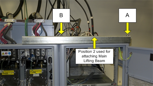
- The main lifting beam slides onto the top of the cabinet. Cables
or hoses may have to be moved out of the way, but none need to be
disconnected, especially for the PEN cabinet. There is a rear bracket
for each position. The main lifting beam hook plate slides into the
rear bracket (shown in Figure 4). Check to ensure that the rear bracket is tight
and secure.Note: The bracket lines up with the support tube's orientation as detailed in . If the bracket is not aligned properly to receive the main lifting beam, then the support tube orientation setup is incorrect for the cabinet.
Figure 4. Cabinet Rear Bracket 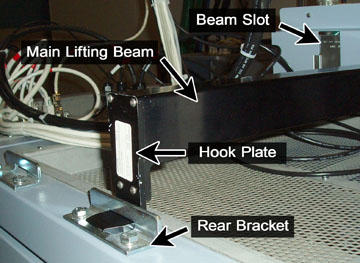
- For the PGR cabinet, remove the gradient cable cover by unscrewing
two screws on each side (shown in Figure 5), then remove
the needed beam slot cover by unscrewing the one thumbscrew (shown
in Figure 6).
Figure 5. Gradient Cable Cover 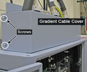
Figure 6. Beam Slot Cover Thumbscrew 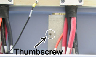
- Slide the winch into the main lifting beam, and secure the winch
in with the pin so it does not slide out. (The winch is able to slide
within the main lifting beam to allow proper alignment with the removed
item or FRU lifting bracket.)
Figure 7. Hoist Kit Assembled 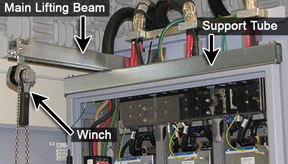
Finalization
- Remove the winch by removing the pin from the main lifting beam and sliding out the winch; place the winch (including hook and chains) into the hoist service kit box.
- Remove the main lifting beam, and return it to the PGR cabinet.
- Insert the hook end of the beam into the cabinet edge first, then place the bottom part of the beam in.
- Secure it into the cabinet with the Velcro straps and pin at the lower end of the beam.
- After the main lifting beam is inserted in the cabinet, plug in the XPS J9 connector on the Z-axis.
- Unscrew the support tube from the top of the cabinet, return it to the HEC, and secure it with the two bolts.