USE PROPER LOTO PROCEDURES BEFORE servicing and/or maintaining this unit.
Warning
possible personal injury or equipment damage!
the module could fall when using the lift tool.
before putting weight on the hoist chain, be sure that the links are aligned properly. this will help keep the chain from binding up, or becoming kinked, which is nearly impossible to correct when the chain is under tension.
Table 6. Required conditions
Condition
Reference
Effectivity
Perform LOTO on the PGR PDU/gradient subsystem before starting this procedure. See the MR Service Safety Manual, 5452735.
-
-
Before disconnecting any coolant lines on the front of the dual drive RF amplifier unit, shut down the Power electronics PuMP (PPMP) at the Heat Exchange Cabinet (HEC).
-
-
About this task
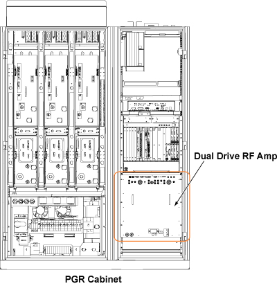
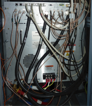
This document describes the dual drive RF amplifier replacement procedure. The amplifier is in the PGR cabinet. The dual drive RF amplifier unit weighs about 335 lb (152 kg), which requires the use of a hoist kit. This document details the correct way to use a hoist kit to safely remove the dual drive RF amplifier unit and replace it with the FRU.
Figure 1. Dual Drive RF Amplifier
Procedure
Power down the host PC.
The power in the cabinet needs to be OFF. Perform LOTO on the PGR PDU/gradient subsystem. See the MR Service Safety Manual, 5452735.
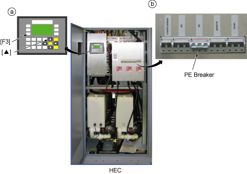
Before disconnecting any coolant lines on the front of the dual drive RF amplifier unit, shut down the PE pump at the HEC by pressing ▲ and F3 simultaneously. Then switch the PE circuit breaker to OFF.
Figure 2. Power Electronics Pump OFF
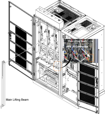
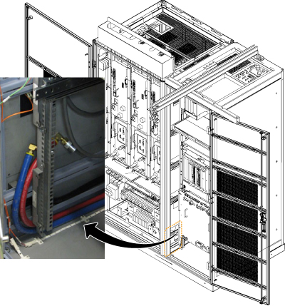
Before setting up the hoist kit, remove the eXtreme Gradient Power Supply (XPS) J9 connector to properly remove the main lifting beam.
Figure 3. Lifting Beam and Connector in PGR Cabinet
Before the next step, prepare to absorb any leakage from the coolant lines by having a towel in hand as the line is connected. Do not allow leakage to fall on the white leak sensor strips located in front of and under the RF amplifier.
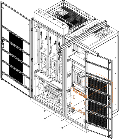
Disconnect the cables on the front of the dual drive RF amplifier, and disconnect the coolant lines.
Figure 5. Disconnecting Cables
Carefully move the cables and lines to the side of the cabinet, allowing the surrounding area to be free from any obstruction of movement for when the amplifier is pulled out.
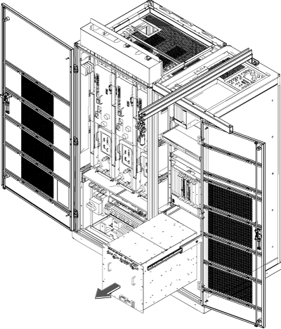
Using the two front handles, carefully slide out the dual drive RF amplifier unit.
Figure 8. Slide Out Dual Drive RF Amplifier
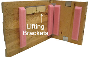
Attach the lifting brackets to both sides of the dual drive RF amplifier. The lifting brackets can be found in the dual drive RF amplifier FRU crate. The attachment screws are captive screws and remain with the lifting brackets.
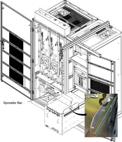
Hook the winch and spreader bar from the hoist kit to the lifting bracket.
Note: Make sure the hook is seated in the lifting bracket. If it is not, the weight can shift, causing harm to the equipment or engineer.
Figure 11. Lifting Brackets with Seated Hook
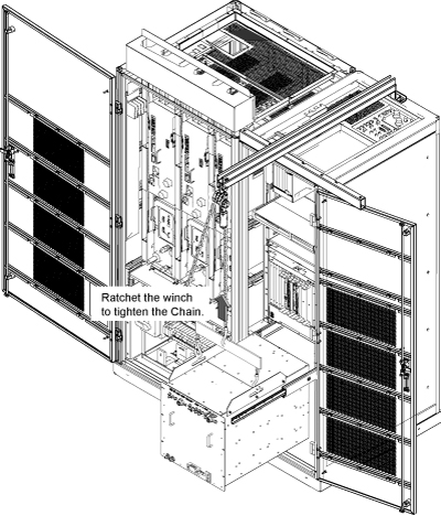
Ratchet the winch to tighten the chain.
Figure 12. Tighten Chain
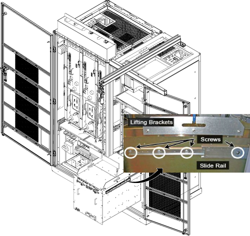
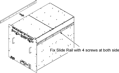
With the dual drive RF amplifier unit supported by the hoist kit, unscrew the four screws and remove the slide rails from both sides.
Figure 13. Dual Drive RF Amplifier Slide Rails
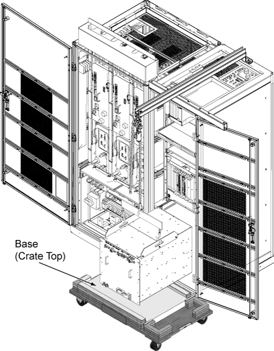
The FRU is packaged in a wooden crate. For the dual drive RF amplifier, there are four parts to the FRU crate. Remove the top of the wooden crate and turn it on its top, so the dual drive RF amplifier being removed can be placed into the top.
Roll the top under the dual drive RF amplifier. Lock the wheels so that the container does not move.
Figure 14. Base of FRU Crate
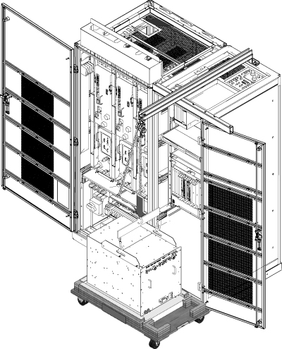
Ratchet the winch to lower the dual drive RF amplifier into the package.
Figure 15. Lower Dual Drive RF Amplifier
Remove the hook from the lifting bracket.
Unscrew the lifting brackets from the sides of the dual drive RF amplifier.
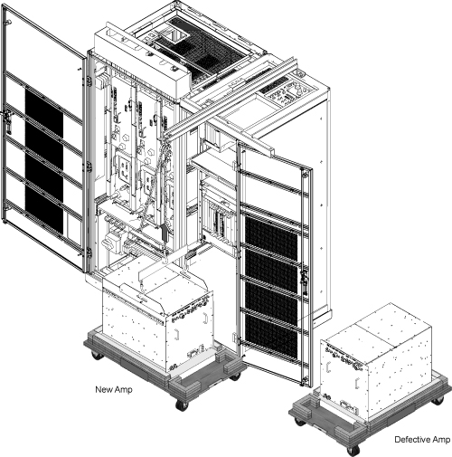
Roll the removed dual drive RF amplifier to the side. Later, it will need to be purged of water coolant before being packaged for return.
Remove the center sections of the FRU crate.
Bring the FRU to the front of the cabinet.
Attach the slide rails to the FRU.
Figure 16. Attach Slide Rails
Attach the lifting brackets to the sides of the new amplifier.
Attach the new dual drive RF amplifier lifting brackets to the winch and spreader bars.
Note: Make sure the hook is seated in the lifting bracket. If it is not, the weight can shift, causing harm to the equipment or the engineer.
Figure 17. Dual Drive RF Amplifier FRU
Ratchet the winch to tighten the chains and begin lifting the unit. Slide out the rail a short amount to determine how high to lift the dual drive RF amplifier. The dual drive RF amplifier slide rails and the cabinet slide rails must align for correct insertion.
When the slide rails are aligned, pull the slide rails out a short distance to get each side started. After both of the slide rails are attached, pull the slide rails onto the FRU until you hear a click. This click is a signal that the unit is docked in the rails. Ensure the dual drive RF amplifier is secure on the rails.
Figure 18. Dock RF Amplifier in Slider Rails
Unhook the winch and spreader bars from the lifting brackets. Remove the lifting brackets from the sides of the new dual drive RF amplifier.
Place the lifting brackets into the dual drive RF amplifier FRU crate.
Slide the dual drive RF amplifier into the cabinet completely.
Attach the dual drive RF amplifier to the cabinet using the front six attachment screws (see Figure 7).
Note: Before the next step, prepare to absorb any leakage from the coolant lines by having a towel in hand as the line is connected. If any coolant leaks onto the white leak sensor strips under the RF amplifier, dry it thoroughly to prevent tripping the PDU rotary main breaker.
Reconnect the remaining cables and coolant lines to the dual drive RF amplifier.
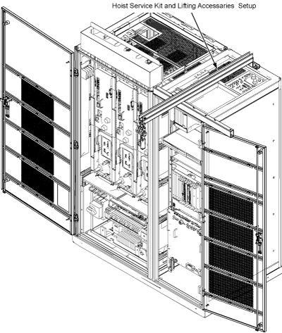
Disassemble the hoist kit. See Hoist Service Kit and Lifting Accessories. Return the main lifting beam to the PGR cabinet. After the beam is secure, reconnect the XPS J9 connector. Return the support tube to the HEC.
Proceed to Finalization.
Finalization
Restore the power and remove LOTO from the PGR PDU/gradient subsystem. See the MR Service Safety Manual, 5452735.
Power up the host PC.
Turn on the PPMP CB at the HEC. Start the pump by pressing ▲ and F3 simultaneously.
To prevent freeze damage to internal coolant pipes during return shipment, remove water coolant from the dual drive RF amplifier unit using the manual coolant removal tool Coolant Draining.
After attaching the center sections of the FRU package to the removed FRU unit base, attach the top of the FRU crate to prepare the FRU for return.
Note: The dual drive RF amplifier has two center sections.