
- Optima MR450w BASE 1.5T System Service Methods
- 5690012-2EN Revision 3
- 00000018WIA30171E20GYZ
- id_131073123.0
- Aug 29, 2019 1:39:30 AM
Coolant draining
Personnel Requirements
| Part | Required Persons | Preliminary Timing (mins.) | Procedure Timing (mins.) | Finalization Timing (mins.) |
| HEC | 1 | 5 | 30 | 5 |
| PGR | 1 | 5 | 30 | 5 |
| XRFD (MR750, MR750w) | 1 | 5 | 5 | 5 |
| XRFD (MR450, MR450w) | 1 | 5 | 5 | 5 |
| XRFD PS (MR750, MR750w) | 1 | 5 | 5 | 5 |
| XPS | 1 | 5 | 5 | 5 |
| XGA | 1 | 5 | 5 | 5 |
| XRM_ (Gradient Coil) | 1 | 5 | 15 - 30 | 5 |
Procedure Overview
This procedure describes how to drain the individual Field Replaceable Units (FRUs) and cabinets containing coolant. These FRUs and cabinets need to be drained when completing certain replacement procedures. The FRUs are located in the Heat Exchanger Cabinet (HEC) and the Power Gradient RF (PGR) Cabinet. Failing to drain the FRU prior to return can irreparably damage it if the residual internal coolant freezes during transit.
Click on the appropriate section link below to go to a particular coolant draining process.
-
Facility Coolant Removal, Gradient Coil Heat Exchanger and Power Electronics Heat Exchanger
-
Gradient Coil Reservoir and Power Electronics Reservoir, Gradient Coil Reservoir and Power Electronics Reservoir
-
Gradient Coil Pump and Power Electronics Pump, Gradient Coil Pump and Power Electronics Pump
-
Removing Coolant from PGR Cabinet, PGR Cabinet
-
XRFD, XPS, and XGA Components, XRFD / XPS and XGA Components
-
XRFD PS Component (MR750 only), XRFD PS Component
-
Removing Coolant from Gradient Coil, Gradient Coil
Preliminary Requirements
Tools and Test Equipment
| Item | Part Number | Quantity |
| Water Removal Pump Kit (located in HEC) | - | 1 |
| 5 gallon Pail with Handle | - | 1 |
| Adjustable Wrench | N/A | 1 |
| Funnel (located in HEC) | N/A | 1 |
Consumables
Towels
Safety
| Warning | |
|---|---|
| Notice | |
|---|---|
| Notice | |
|---|---|
Required Conditions
Condition: If draining the entire or part of a system for a replacement procedure, follow the appropriate Lock Out/Tag Out (LOTO) instructions for that cabinet or part.
Condition: Pumps must be powered off before coolant is drained.
Procedure
Removing Coolant from Heat Exchanger Cabinet
Facility Coolant Removal
| Notice | |
|---|---|
-
Disable the Magnet Monitor to prevent false alarms if HEC power is locked and tagged out.
-
Before draining the primary coolant loop (facility side), ensure the facility coolant is isolated from the HEC.
Note:Check with the facility owner to determine the proper shutdown method for the chiller.
-
After isolating the facility coolant, place the open end of the drain hose into the pail.
Note:The primary cooling loop is drained from the HEC through the gradient coil heat exchanger quick disconnect or the power electronics quick disconnect located at the bottom of each heat exchanger shown in Figure 4. (The power electronics quick disconnect is located to the right of the power electronics tank in a position similar to the gradient coil tank.)
The cryogen compressor filter is located at the top of the cabinet. (See Figure 2 for an example of the old style, or Figure 3 for an example of the new style.)
Figure 2. Cryogen Compressor Filter - Old Style 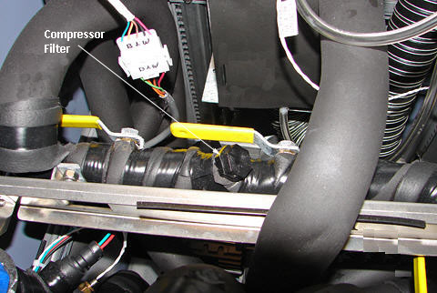
Figure 3. Cryogen Compressor Filter - New Style 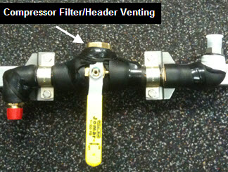
-
Connect the drain hose to the gradient coil heat exchanger quick disconnect or power electronics heat exchanger quick disconnect. (See Figure 4.)
Figure 4. Heat Exchanger Quick Disconnect 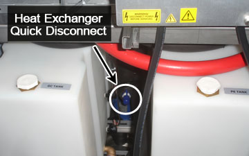
-
Vent the header.
For Old Style Compressor Filter: Remove the cryogen compressor filter to vent the header.
For New Style Compressor Filter: Remove the hex head cap and turn the valve handle at a 45-degree angle to vent the header and drain facility coolant. (See Figure 5.)
Figure 5. Valve Handle at 45-Degree Angle 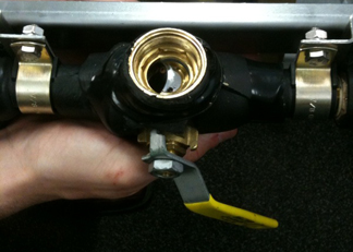
-
Once the pail is filled, close the 1-1/2 in. ball valves on the HEC supply and return headers.
-
Follow local regulations for proper disposal of coolant.
-
Open the 1-1/2 in. ball valves to continue the draining process until the primary cooling loop is completely drained (fluid stops running from the drain hose).
Gradient Coil Reservoir and Power Electronics Reservoir
| Notice | |
|---|---|
-
Disable the Magnet Monitor to prevent false alarms if HEC power is locked and tagged out.
-
Place the open end of the drain hose into the pail.
-
Connect the female quick disconnect end of the drain hose to the main disconnect of the Gradient Coil (GC) reservoir or the Power Electronics (PE) reservoir shown in Figure 6 (Ebara pump) or Figure 7 (Price pump).
Figure 6. Reservoir and Pump Items (Ebara Pump) 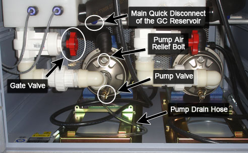
Figure 7. Reservoir and Pump Items (Price Pump) 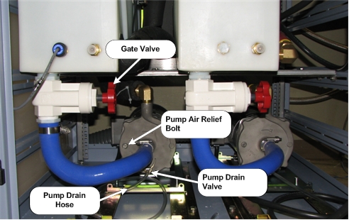
-
Drain the coolant:
-
Remove the reservoir cap and allow the coolant to drain until the pail is full.
-
Disconnect the quick disconnect when the coolant fills the pail.
-
Follow local regulations for proper disposal of the coolant.
-
Reconnect the quick disconnect and continue draining into the pail.
-
Repeat this step until the reservoir is empty.
Note:The gradient coil cooling circuit may continue to fill the reservoir after emptying the reservoir. Repeat as necessary until coolant is completely removed.
-
-
Before restarting the pump, make sure the gate valve at the bottom of the respective reservoir is open and there is coolant in the suction line to the pump.
Gradient Coil Pump and Power Electronics Pump
| Notice | |
|---|---|
Refer to Figure 6 (Ebara pump) or Figure 7 (Price pump) for the following steps.
-
If replacing the pump, close the gate valve below the GC or PE reservoir.
-
Place the open end of the small hose, located at the bottom of the GC or PE pump, into the pail.
-
Open the valve on the small hose of the GC or PE pump.
-
Remove the pump air relief bolt on the front of the pump to allow the coolant to flow. See Figure 6 (Ebara pump) or Figure 7 (Price pump).
-
When the coolant is done draining, close the valve and replace the bolt on the pump.
-
Before pump is restarted, make sure the gate valve at the bottom of the respective reservoir is open and there is coolant in the suction line to the pump.
-
Follow local regulations for proper disposal of coolant.
Removing Coolant from PGR Cabinet
XRFD, XPS, and XGA Components
| Notice | |
|---|---|
-
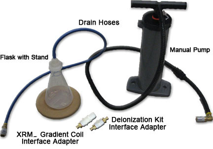
Place the open end of the drain hose into the pail.
-
Connect the other end of the drain hose to the quick disconnect on one of the components (XRFD, XPS or XGA).
-
Connect the manual hand pump to the other component quick disconnect.
-
Pump the manual pump to remove the coolant.
-
Use the funnel to pour the coolant into the flask and measure the amount of coolant removed. (See Table 1 for the amount of coolant to be removed based on the component.)
-
Follow local regulations for proper disposal of coolant.
| Component | Amount to Drain |
| XGA | 210 ml |
| XPS | 220 ml |
| XRFD (MR750, MR750w) | 1000 ml |
| XRFD (MR450, MR450w) | 150 ml |
| XRFD PS (MR750) | 130 ml |
XRFD PS Component (MR750 only)
| Notice | |
|---|---|
-
Hook the pump up to the supply side of the XRFD PS and the drain hose to the return side. No adaptors are needed.
-
Place the open end of the drain hose into the pail.
-
Pump the manual pump to remove the coolant levels specified in Table 1.
-
Use the funnel to pour the coolant into the flask and measure the amount of coolant removed. The XRFD PS requires 130 ml of coolant removed.
-
Follow customers procedure for proper disposal of coolant.
Removing Coolant from Gradient Coil
Refer to applicable gradient coil replacement procedure for removing of coolant.
Finalization
-
Re-enable Magnet Monitor.
-
Make sure all coolant tanks are filled to their appropriate fluid levels.
-
Return the Water Removal Pump Kit to the HEC.