Install a table interface (TIF) assembly in the magnet outer electronics.
Prerequisites
| Personnel requirements |
|---|
| Required persons | Preliminary requirements | Procedure | Finalization |
|---|
| 1 | - | 10 minutes | - |
| Tools and test equipment |
|---|
| Item | Quantity | Part number | Manufacturer |
|---|
| Nonmagnetic Titanium Service Tool Kit, Small Set | 1 | 5113258 | - |
| Replacement parts |
|---|
| Item | Quantity | Part number | Manufacturer |
|---|
| Table Interface Module (RoHS) | 1 | 5176474-51 | - |
Procedure
- Apply anti-seize to three screws.
- Install the TIF assembly onto the magnet side electronics plate.
- Install the three M6 x 12 Phillips Head Screws securing the TIF to the side electronics plate.
Figure 1. Table interface screws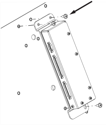
- Connect cable M3351 to TIF J5.
Note: Route M3351 over the top of the TIF.
Figure 2. (For AR magnets) M3351 route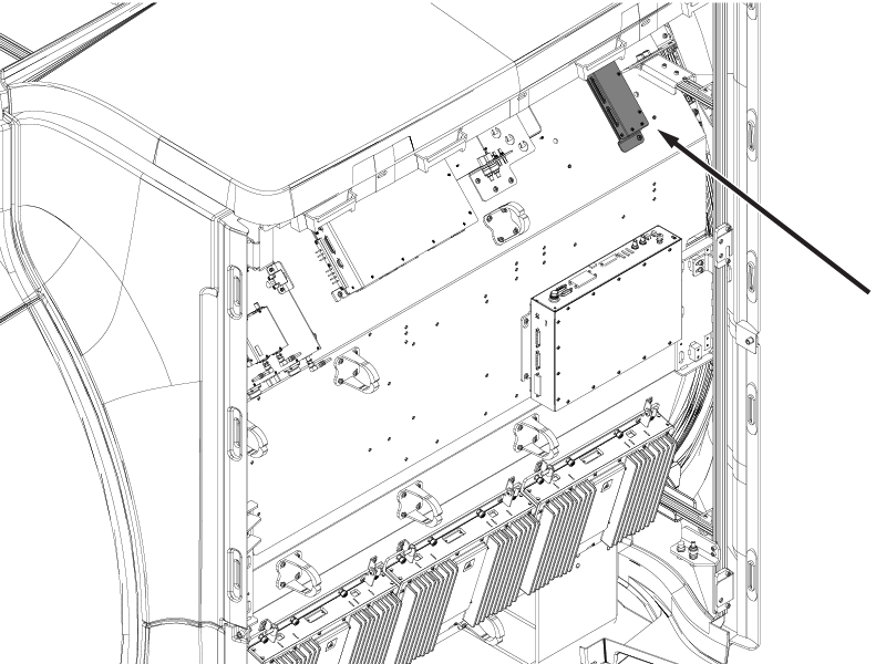 Figure 3. (For UA magnets) M3351 route
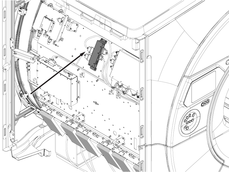
- If the table dock is installed, connect J1, J2, J3, and J6.
