For software version PX26 and earlier: To run this test, use System Gain Calibration. For software PX28 and later, use this procedure.
System gain calibration determines the body and T/R (transmit/receive) head recon scale factors that will achieve a known level of image intensity when you use the body and T/R head coils with a known phantom solution and protocol. The goal is that when the same solution or tissue is scanned in the standard body and T/R head coils with the same protocol, those tissues will have approximately the same image intensity level on a given system and between systems of like type.
This calibration accounts for differences in body receive coil and T/R head coil sensitivity, preamp gains, cable loss, receiver gain, and other factors. The calibration must be done on the body at least once to calibrate those paths.
Procedure
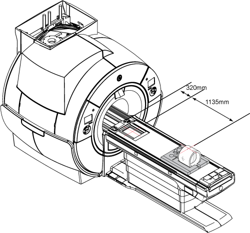
Move the cradle 320 mm from the home position and landmark, but do not advance to scan.
Run the cradle in so the display reads 1135 mm.
Figure 1. Distance between landmark and center mark on body loader
Put the body loader on the Service Foam Positioner. Turn on the alignment light and then position the body loader on the cradle so that the alignment light is properly centered on the loader crosshair.
Do not landmark after completing this step.
Press Advance to Scan.
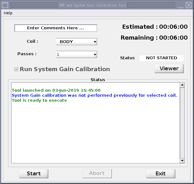
Start the system gain calibration tool from the Common Service Desktop: Select Calibration > System Gain Calibration and click Click here to start this tool.
The SNR and System Gain Calibration Tool window shows.
Note: You can enter text into the Comments field.
Keep BODY as the Coil value.
Select the Run System Gain Calibration checkbox.
Select the Start button.
Figure 2. Run system gain calibration (example)
Result
The calibration starts. After it is complete, the tool window shows that the calibration is completed. If adjustments are necessary, the system asks, Do you want to save the recon scale factor?