- id_13106522
- Version: 3.0
- Date: Jul 17, 2019 6:08:32 PM
Laser light alignment
Prerequisites
| Required persons | Preliminary requirements | Procedure | Finalization |
|---|---|---|---|
| 1 | Not Applicable | 10 minutes | Not Applicable |
| Item | Quantity | Effectivity | Part number | Manufacturer |
|---|---|---|---|---|
| Non-Ferrous Allen Wrench Set | 1 | - |
|
- |
| Non-Ferrous Flat Blade Screwdriver | 1 | - |
|
- |
Procedure
- Verify that the bridge is centered. If not, center the bridge. Please see Bridge and Longitudinal Drive Belt Replacement procedure, and refer to the “X-Direction Bridge Alignment” and the “Z-Direction Bridge Alignment” sections.
- Press the Alignment button on the control panel to turn on the laser light.
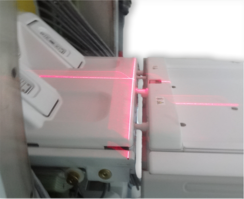
- Check for proper alignment. The axial light should align with
the joints of the bridge endcap and bridge on each side of the bridge
and the sagittal light should align with the middle of the LPCA and
the middle of the table. If alignment is correct, you are done with
this procedure. Otherwise, continue with the steps that follow.
Figure 1. Proper alignment
- For an In-Room display, remove the laser light cover by removing
the two screws shown. The cover is held in place by two poppers (one
in each lower corner of the laser cover).
Figure 2. Remove laser cover
- Adjust the alignment via the joystick so that the axial light
(x-axis) is aligned to the bridge and endcap joints on both sides
of the bridge and the sagittal light (z-axis) is centered down the
middle of the bridge. See Figure 1 for proper alignment.note: There is only one joystick to adjust the laser light.
Figure 3. Adjusting laser lights with single joystick
- Replace the trim ring as appropriate.
Finalization
- Complete DQA Calibration to calibrate isocenter by following the instructions in Troubleshooting the Daily Quality Assurance (DQA) II tool.
- If this is an adjustment and no further calibrations are needed, then complete a SAVEINFO to save current system calibrations.