- id_15271087
- Version: 2.7
- Date: Jul 5, 2019 10:35:42 AM
Grafidy 3 Eddy Current Calibration
Prerequisites
| Required persons | Preliminary requirements | Procedure | Finalization |
|---|---|---|---|
| 1 | Not Applicable | 60 minutes | Not Applicable |
| Item | Quantity | Effectivity | Part number | Manufacturer |
|---|
| Item | Quantity | Effectivity | Part number | Manufacturer |
|---|---|---|---|---|
| Not applicable | 0 | - | - | - |
|


| Condition | Reference | Effectivity |
|---|---|---|
|
DQA II tool within specification |
- | |
|
Shim within specification for rough shim. |
- | - |
Overview
Disclaimer: Depending on your service agreement, not all service tools, diagnostics, and utilities referenced in this document may be accessible. Contact your sales person for information on available service license packages.
Grafidy 3 adjusts and compensates short, long, and very long time constant eddy currents for both linear and B0 terms. Use the Grafidy 3 procedure to perform eddy current compensation. Grafidy 3 should be run in Auto mode first. If Auto mode fails to bring any of the terms into specification, Manual mode and Oscillatory mode can be used.
Grafidy 3 uses a dedicated pulse sequence, six-channel fixture, and Grafidy 3 software. The Grafidy 3 fixture plugs into the LPCA for transmit/receive. No additional fixtures or cables are needed.
This tool simplifies setting up the calibration and collects data from all six coils simultaneously. The basic steps required in Grafidy 3 are:
-
Set up the six-channel Grafidy fixture.
-
Start Grafidy 3 and run the tool in Auto mode.
-
If Auto mode does not bring all terms into specification (still red in the Result/Area table), proceed to Oscillatory mode in Oscillatory Mode.
Hardware Setup
Procedure
- Unfold the six-channel Grafidy fixture and lock the arms into place (90° from center plate).
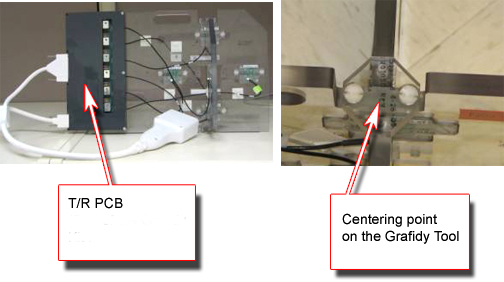
- Connect the Hypertronics cable to the T/R board and secure with screws. Place the fixture at the front (head coil end) of the table with the connection box toward the bore.
-
(For systems with DPP receive chain) Connect
P-port connector to P1 port on the LPCA.
Figure 1. Grafidy Hardware Setup for Flat Table
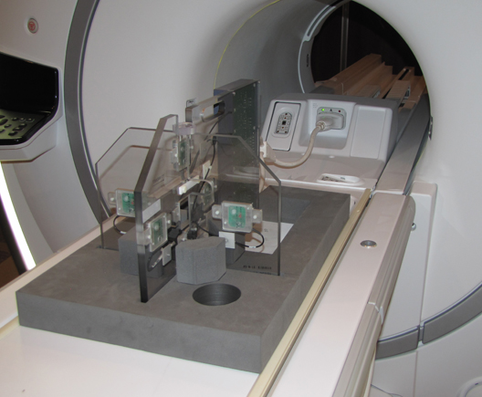
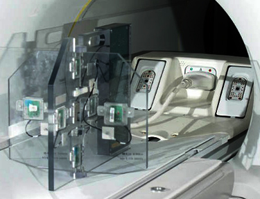
Figure 2. Grafidy Hardware Setup for Curved Table
- Center the laser crosshairs on top of the fixture. Landmark
the system and press Advance to Scan.
Figure 3. Grafidy Tool and Centering Point
Running Grafidy 3
Procedure
- From the Common Service Desktop, navigate to Calibration > Grafidy3.
- Select the Auto Mode tab. All three coil axes are selected automatically.
- Click the Scan button to start the calibration.
-
When the scan is active, it can be stopped by pressing the Abort button and the STOP button on the keyboard.
-
Highlight the desired axis and select Show to display the result graphs. Or, on the Oscillatory tab, click Show Oscil to display the oscillatory graphs.
Figure 4. Auto Mode Setup
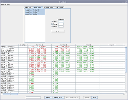
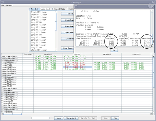
The Grafidy 3 software runs multiple scans to bring each term into specification. It iterates up to the maximum amount specified (default is five iterations). When each component finishes a scan/analysis iteration, the residual of the eddy current of the measurement displays in the results table. The results are color-coded.
Text Color Definition Red Values above specification Green Within specification -
- Review the numeric output values from the Auto mode scan. Verify
that the results of the final iteration for each component are within
specification (green).
Figure 5. Reading Output with Specifications and Actual Values (Smoothed)
- If a component is not within specification after the maximum number of iterations, use Manual mode to calibrate that component.
Manual Mode
Manual mode allows you to iterate through the process and decide when to stop.
Procedure
- Select the Manual Mode tab.
Figure 6. Manual Mode Tab
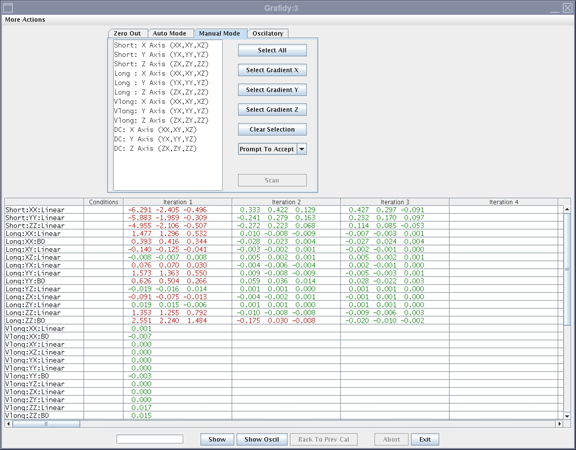
- Select the desired terms, and press Scan.
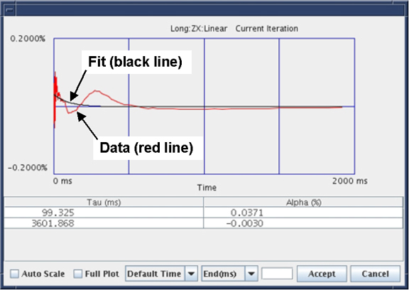
- If the Prompt To Accept mode is active,
a graph of the results displays after the scan is completed.
- If a good fit is displayed (fit line aligned with data line), click Accept. The calibration values are saved to disk, and used in the next scan. Repeat this process by setting desired terms for the next scan and select Scan.
- If a bad fit is displayed, click Cancel.note:
This leaves the last accepted values in the calibration files. Do not expect any improvement on future scans when the fit does not match the data, even if the Cal parameters are accepted.
Figure 7. Results Window with Accept/Cancel Buttons
- The last iteration for any component must be a check only. Do not accept the fit parameters. You will not be allowed
to exit immediately after updating the Cal parameters.
If problems are encountered or if it is out of specification after Auto mode, it may be necessary to run Oscillatory mode, outlined in the next section.
Oscillatory Mode
NOTE: After you complete the tool in Auto or Manual mode the tool will automatically enable the Oscillatory Mode. Oscillatory mode needs to be run ONLY when there is any failure seen with any of the Long compensation terms in either Auto Mode or Manual Mode. Oscillatory Mode will not help to improve the system eddy current compensation, when it is run without having any of the Long mode failure from the Auto or Manual mode, rather it could cause some harm to the system eddy current compensation.
Procedure
- If the Oscillatory tab is enabled, proceed to Step 5. Otherwise, continue with the following steps to enable Oscillatory Mode.
- Close the Grafidy tool if it is open from the previous Manual or Auto Mode run.
- Add the following flags to /usr/g/bin/graf3/graf3.init file
to enable the Oscillatory compensation in Grafidy.
- Open a C-shell.
- Type cd /usr/g/bin/graf3.
- Type gedit graf3.init.
- Add the following flags and set the values to 1 as shown below:
-
oscil_xx_flag = 1
-
oscil_xb0_flag = 1
-
oscil_yy_flag = 1
-
oscil_yb0_flag = 1
-
oscil_zz_flag = 1
-
oscil_zb0_flag = 1
-
- Save the file and exit from gedit.
- Launch the Grafidy tool.
- Select the Oscillatory tab.
- Uncheck all of the checkboxes except for terms that failed from
Auto or Manual modes. For example, if you only noticed the Long YB0
failure from the Auto or Manual mode, check only YB0 and not the other
terms.
Figure 8. Oscillatory Mode Tab
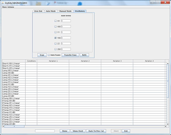
- Enter 3 as the number of terms for each checked item.
- Click Transfer Func. The tool will acquire seven iterations of data to calculate the transfer function. Wait until the scan completes.
- After the transfer function is complete, select Scan. A scan is performed, followed by a fit, and followed by another
scan. (This process takes approximately 10 minutes.)note:
After a scan is complete, the screen remains inactive while software is performing the fit. The screen becomes active after fit and final scan are completed. Be patient and wait for the screen to become active.
- After the scan is complete, select the Manual Mode tab. Select only the Long mode for the failed axis from the last Manual or Auto mode and click Scan.note:
This step will check and confirm whether the applied Oscillatory compensation working or not. If you see the failure even after this, then the Oscillatory compensation needs to be run again with higher number of terms. In this case, follow the steps below.
- Select the Zero Out tab and zero out only the Oscillatory Terms.
- Select the Oscillatory Mode tab and repeat from Step 6 to Step 9, increasing the number of terms to 5 in Step 7.
Finalization
Procedure
- Save Grafidy 3 eddy current data to SaveInfo media.
- Exit the software tool, saving the eddy current data.
- Remove the Grafidy fixture from the system.
If applicable, remove the service filler panels from the table.