
- SIGNA™ Hero 3.0T Service Methods
- 5852800-8EN Revision 1.0
- 00000018WIA30387640GYZ
- id_20145681.16
- Jul 12, 2021 1:03:00 PM
Removing the Global Operator Cabinet (GOC) Power Distribution Unit (PDU) - Dell T5810
Procedure
- Remove the GOC cover screws.
Figure 1. Remove the service cover and disconnect ground cable 
1 Cover screws (2) 2 Service cover 3 Ground wire - Set the GOC PDU breaker CB1 to OFF.
Figure 2. GOC PDU breaker (shown in ON position) 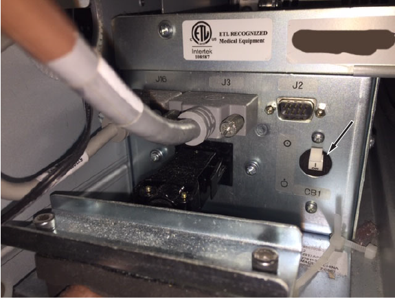
- Disconnect E3018 from J3, E3049 from J2, and J16.
Figure 3. Disconnect the system cable on left-rear side 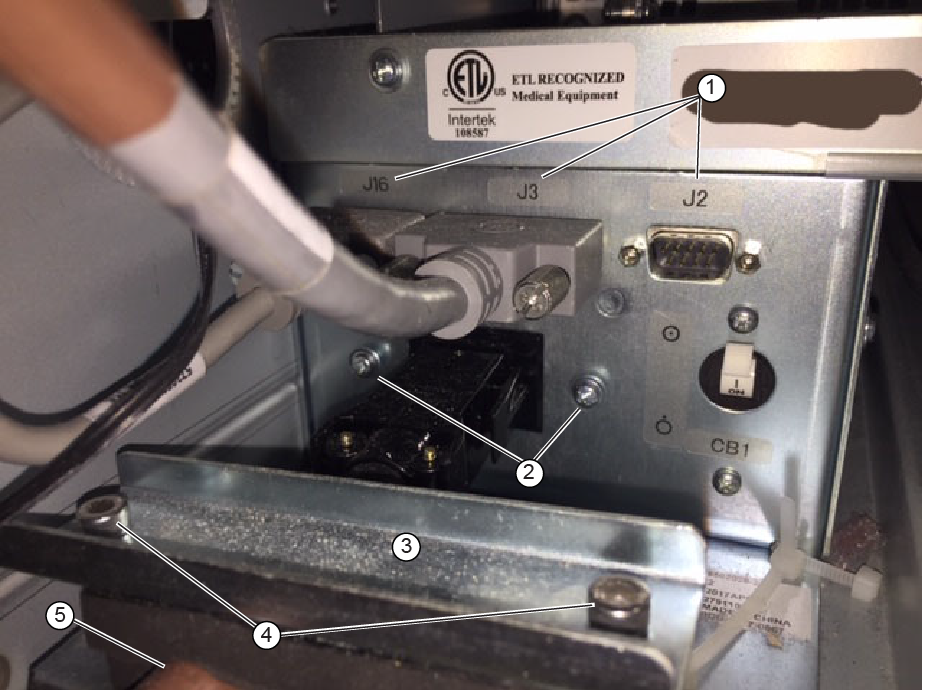
1 J16, J3 (E3018) and J2 (E3049) 2 Cable cover screws 3 Cable fixing bracket 4 Cable fixing cover screws (2) 5 Power distribution supply wire E0003, J1 - Disconnect all cables connected to the GOC PDU in the lower right side.
Figure 4. Disconnect the GOC PDU cables 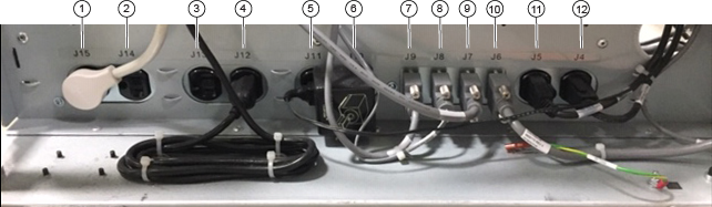
1 J15: Not used. Do not use this outlet for servicing 2 J14: Not used. Do not use this outlet for servicing 3 J13: Not used. Do not use this outlet for servicing 4 J12: Ethernet hub for older GOCs that include an 8-port hub Not used for newer GOC without a hub. Do not use this outlet for servicing
5 J11: Not used. Do not use this outlet for servicing 6 J10: Patient alert box 7 J9: System power on switch 8 J8: Temp/humidty sensor 9 J7: HDMI splitter 10 J6: USB serial port 11 J5: Host computer power 12 J4: To ISC - Remove the two screws securing the rear plate and remove the rear plate.
Figure 5. Remove the GOC PDU 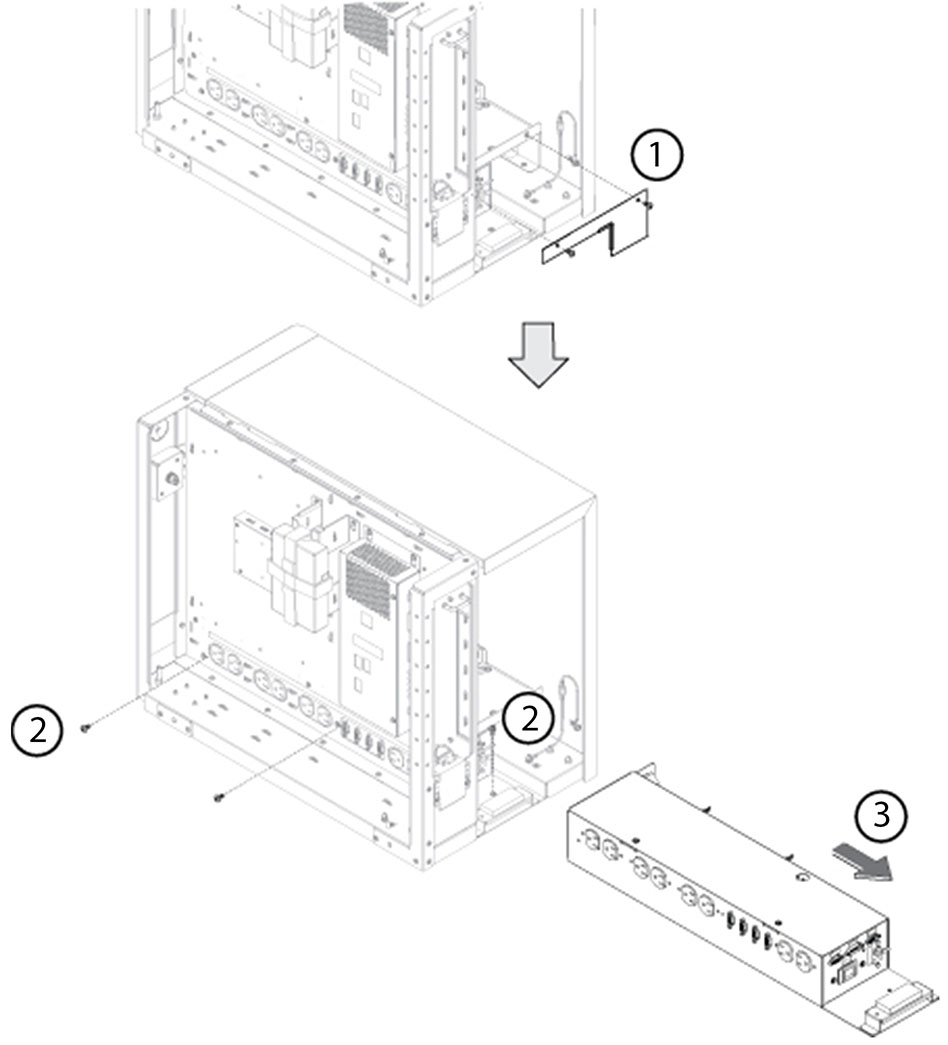
1 Rear plate and screws (2) 2 PDU screws (note the two different locations, two on the side and one in front of the PDU) 3 GOC PDU