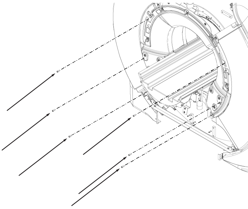
Align rear endbell with rear of magnet with patient cooling air connection pointing up.
Install the rear endbell onto the magnet.
Install six M10 x 25 Socket Head Cap Screws.
Figure 1. Rear endbell screws
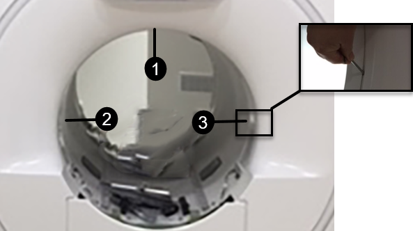
Check the gap between the endbell and the RF coil at the 12 o'clock, 9 o'clock, and 3 o'clock positions using a 3 mm and 4 mm hex wrench. The gap should be 3 mm to 4 mm. If the gap between the rear endbell and RF coil is less than 3 mm or greater than 4 mm, adjustment is required.
Figure 2. Rear endbell gap check locations
1
12 o'clock position
2
9 o'clock position
3
3 o'clock position
Rear endbell gap adjustment
Note the areas that need adjustment and determine how much adjustment is needed.
Remove the rear endbell and set aside.
Loosen the nut on the standoffs that will be adjusted, typically those nearest the area where the gap is incorrect. You may need to remove additional screws.
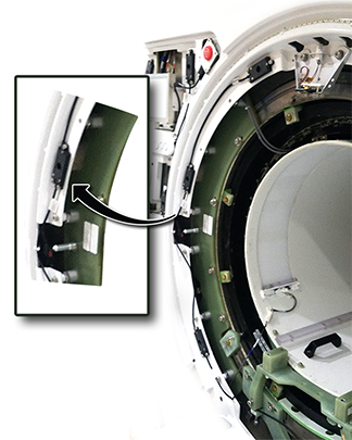
Insert a screwdriver in the nylon screw and turn clockwise to reduce the gap or counterclockwise to increase the gap.
Tighten the silver nuts and reinstall the screws that were removed.
Reinstall the endbell and recheck the gap. Repeat until the gap is 3 mm to 4 mm.
Figure 3. Nylon screw adjustment (patient end shown, adjustment is the same)
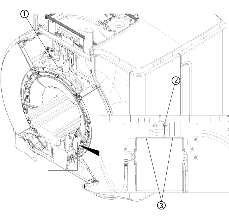
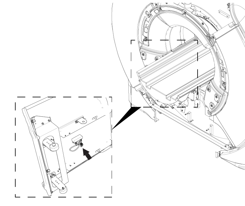
Connect the cable connector to the speaker.
If previously installed, connect patient cooling air hose to the rear endbell.
Figure 4. Rear endbell connections
1
Patient cooling air connection
2
HEX temperature sensor connector
3
Body coil cooling air connections
Connect the cooling air hoses to the body coil.
Connect the HEX temperature sensor connector.
Notice
Component damage
The heat exchanger temperature sensor cable is highly susceptible to damage.
Use caution when connecting, disconnecting, or working around the heat exchanger temperature sensor cable.
If previously installed, connect the cable connectors to the end of travel switch.