- SIGNA™ Hero 3.0T Service Methods
- 5852800-8EN Revision 1.0
- 00000018WHA30BB62GYZ
- id_200143311.7
- Jan 19, 2022 2:53:53 AM
Installing the front endbell
Installs the front endbell onto the magnet.
Prerequisites
| Personnel requirements | |||
|---|---|---|---|
| Required persons | Preliminary requirements | Procedure | Finalization |
| 1 | - | 5 minutes | - |
| Tools and test equipment | |||
|---|---|---|---|
| Item | Quantity | Part number | Manufacturer |
| Nonmagnetic Titanium Service Tool Kit, Small Set | 1 | 5113258 | - |
| Required conditions |
|---|
| Front cover is installed. |
Procedure
- Set remote latch release levers to the latched position.
Figure 1. Remote latch release levers 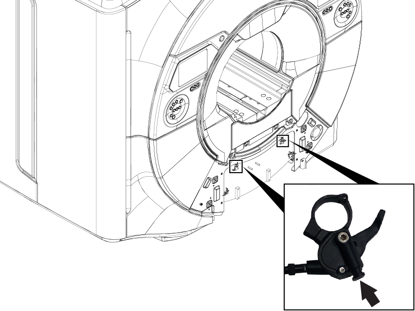
- Align the six remote latch pins on the front endbell with the six remote latches on the front cover.
Figure 2. Remote latch alignment 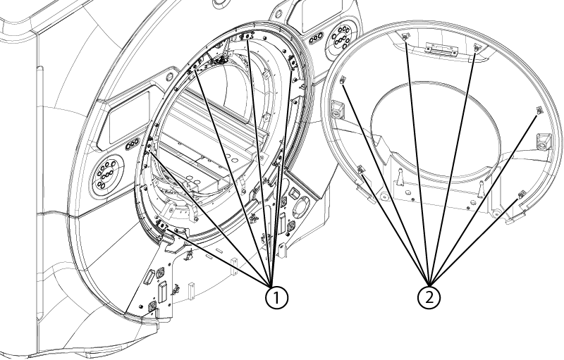
1 Remote latches 2 Remote latch pins - Check the gap between the endbell and the RF coil at the 12 o'clock, 3 o'clock, and 9 o'clock positions using a 3 mm and 4 mm hex wrench. The gap should be 3 mm to 4 mm. If the gap between the front endbell and RF coil is less than 3 mm or greater than 4 mm, adjustment is required.
Figure 3. Front endbell gap check locations 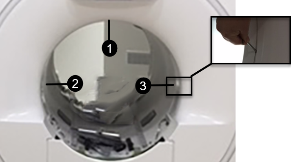
1 12 o'clock position 2 9 o'clock position 3 3 o'clock position - Front endbell gap adjustment
- Note the areas that need adjustment and determine how much adjustment is needed.
- Remove the front endbell and set aside.
- Loosen the nut on the standoffs that will be adjusted, typically those nearest the area where the gap is incorrect. You may need to remove additional screws.
- Insert a screwdriver in the nylon screw and turn clockwise to reduce the gap or counterclockwise to increase the gap.
- Tighten the silver nuts and reinstall the screws that were removed.
- Reinstall the endbell and recheck the gap. Repeat until the gap is 3 mm to 4 mm.
Figure 4. Front endbell gap adjustment 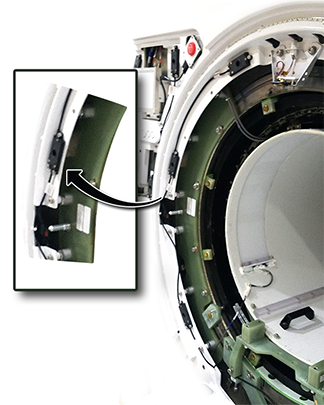
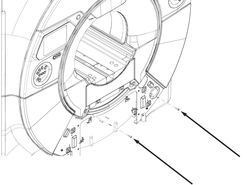
- Install two
M10 x 25 Socket Head Cap Screws securing the front endbell to the magnet.
Figure 5. Front endbell screws