
- SIGNA MR355 / SIGNA MR360
- Service Manual
- 5856356-3EN Revision 5.0
- Basic Service Documentation. Copyright General Electric Company.
- 00000018WIA30DA1030GYZ
- id_131064491.7
- Oct 23, 2019 3:02:57 AM
Replacing BRM-D (Short) RF Body Coil
Prerequisites
| Required persons | Preliminary requirements | Procedure | Finalization |
|---|---|---|---|
| 2 | Not Applicable | 3 to 5 hours | Not Applicable |
| Item | Quantity | Effectivity | Part number | Manufacturer |
|---|---|---|---|---|
| Non-Magnetic Tools | 1 | - |
2385097 or 5112581 | - |
|
Personal Protection Equipment (PPE) composed of: Gloves Safety Glasses Safety Shoes Long Sleeve Shirts and Pants | 1 | - |
- | - |
| 1 | - | - | - | |
| 1 | - | - | - | |
| 1 | - | - | - | |
| 1 | - | - | - | |
| Authorized Personnel Floor Sign | 1 | - |
2289812 | - |
| Item | Quantity | Effectivity | Part number | Manufacturer |
|---|---|---|---|---|
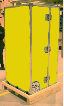
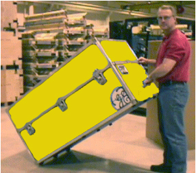
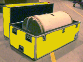
| 1.5T Short Body RF Coil and Yellow Case | 1 | 1.5T systems |
2208999-17 | - |
| ||||||||
| Condition | Reference | Effectivity |
|---|---|---|
|
The following components must be removed prior to RF coil replacement: |
Bridge Front Endbell Rear Endbell | - |
|
For steps prior to the actual RF Coil replacement for systems with a Cx or LCC magnet, refer to Failed Gradient Body Coil Removal. | - | - |
About this task
The RF body coil cartridge is a Field Replaceable Unit (FRU) that mounts inside the gradient coil (also a FRU). It is available in 1.0T and 1.5T versions. If the RF coil fails, it must be removed from the gradient coil and replaced. Since the replacement procedures for the RF and gradient coils are closely related, references are made below to the epoxy-filled gradient coil replacement procedure where instructions for removal of similar parts (for example, the bridge) can be found. While a portion of the following procedure can be accomplished by one person (connecting/disconnecting various cables, etc.), replacing a failed RF body coil requires more than one person.
Only trained and qualified engineer can execute this procedure.
Unpacking BRM-D (Short) RF Body Coil
Replacing BRM-D (Short) RF Body Coil
Procedure
- Remove the RF Body coil from the CRM without using the RF tracks,
which are too thick to use. Use pieces of smooth, stiff material (sheets
of film work well) to easily slide the RF coil out of the Gradient
Coil. See Figure 4 through Figure 14 for removing and replacing the BRM-D RF Body Coil.
Figure 4. Loosening BRM-D (Short) RF Body Coil Overview 
Figure 5. Loosening BRM-D (Short) RF Body Coil Detail 
Figure 6. Release the Latch Assembly 
Figure 7. Latch Assembly Detail 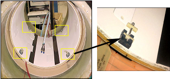
Figure 8. Release the RF Constraints 
Notice 
Figure 9. Removing BRM-D (Short) RF Body Coil 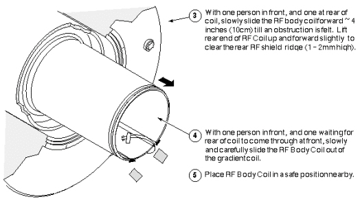
Figure 10. Installing BRM-D (Short) RF Body Coil 
Figure 11. Installing the BRM-D (Short ) RF Body Coil 
Figure 12. Positioning the BRM-D RF Body Coil 
Figure 13. Installing the RF Constraints (Additional Detail) 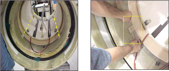
Figure 14. Securing BRM-D (Short) RF Body Coil 
- Route RF cable along left side of the plate, securing in position
using cable mounts (PN 46-208747P1) and cable ties (PN 46-252283P68)
on front support plate.
Figure 15. Route RF cable 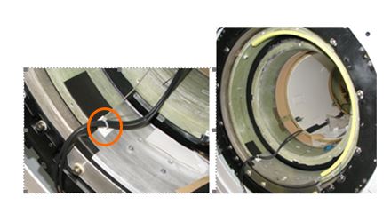
- Connect the RF cable J3/J4 which is coming up from body coil
to cable 2018/2019( D-D bias cable) which is coming up from under
the magnet.
Figure 16. RF cable Connection 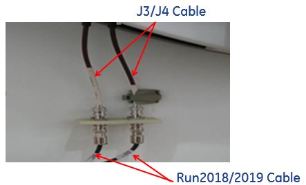 Note:
Note:Do not have a loop or slack when connecting the D-D bias cable to the body coil cable.
Finalization
Procedure
- Install all removed components.
- Clean up the site in preparation for patient scans.
- Perform TR Dynamic Disable Calibration.