
- SIGNA MR355 / SIGNA MR360
- Service Manual
- 5856356-3EN Revision 5.0
- Basic Service Documentation. Copyright General Electric Company.
- 00000018WIA30A70030GYZ
- id_131068091.4
- Jul 5, 2019 11:49:11 PM
Gradient Coil Replacement Preparation
Prerequisites
| Required persons | Preliminary requirements | Procedure | Finalization |
|---|---|---|---|
| 3 | Not Applicable | 3-5 hours | Not Applicable |
| Item | Quantity | Effectivity | Part number | Manufacturer |
|---|---|---|---|---|
| Gradient Insertion Tool Kit Information | 1 | - |
2164744-5 | - |
| BRM/BRM-D/CRM Cart | 1 | - |
2134810 | - |
| Aluminum Cradle | 1 | - |
2134810-2 | - |
| Cable Crimper/Stripper Kit | 1 | - |
2134776 | - |
| Poron Seal, for air cover | 1 | - |
2185175 | - |
| Poron Seal | 4 | - |
2181231 | - |
| Poron Seal | 8 | - |
2181231-2 | - |
| Splice kit | 1 | - |
2241521 | - |
| Non-Magnetic Tools | 1 | - |
2385097 or 5112581 | - |
|
Personal Protection Equipment composed of: Gloves Safety Glasses Safety Shoes Long Sleeve Shirts and Pants | 1 | - |
- | - |
| 1 | - | - | - | |
| 1 | - | - | - | |
| 1 | - | - | - | |
| 1 | - | - | - | |
| 5 Gallon Bucket to Collect Coolant | 1 | - |
2239133 | - |
| Authorized Personnel Floor Sign | 1 | - |
2289812 | - |
| Aluminum Support Bracket - Front | 1 | - |
2213168-3 | - |
| Aluminum Support Bracket - Rear | 1 | - |
2213167-3 | - |
| Item | Quantity | Effectivity | Part number | Manufacturer |
|---|---|---|---|---|
| Red Loctite # 271 | 1 | - |
46-170686P3 | - |
| Blue Loctite # 242 | 1 | - |
46-170684P2 | - |
| Ty-wraps | 5 | - | - | - |
| Isopropyl Alcohol | 6 oz | - | - | - |
| RTV 102 (Europe) | 1 | - |
46-170617P1 | - |
| RTV 108 (Americas) | 1 | - |
46-170619P1 | - |
| Tack Cloth | 2 | - | - | - |
| ||||||||
| Condition | Reference | Effectivity |
|---|---|---|
|
Gradient coil is removed from the magnet using Defective Gradient Removal Procedure. | - | - |
Procedure
- Remove the Tube and the two Tube Guide Roller Assemblies from
the defective Gradient coil and install one onto each end of the new
Gradient Coil Assembly. Note:
Do not reuse the mounting brackets with gussets. See Figure 1.
Figure 1. Gradient Brackets with Gussets 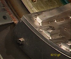
- On the new gradient, do the following:
- Clean the bolt threads by using a tack cloth to perform a back
forth motion clockwise/counterclockwise around the threads as shown
in Figure 2. Ensure any loose debris in the bolt threads is removed.
Figure 2. Bolt Cleaning Procedure 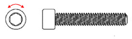
- Clean underside of BRM bracket (2213168-3) by using a tack cloth
as shown in Figure 3. Make sure that the underside of the bracket is free of any metallic
particles.
Figure 3. BRM Support Bracket Cleaning Procedure 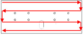
- If the BRM bracket only uses 4 bolts then fill the 4 unused
bolt holes with caulk as shown in Figure 4. Wipe away excess
caulk so that the caulk is flush with the bracket’s surface
as shown in Figure 5.
Figure 4. Unused Bolt Hole Caulking Locations (if applicable) 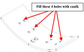
Figure 5. Close-up of Unused Bolt Hole Filled with Caulk 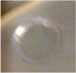
- Apply caulk to the periphery of the bracket as shown in Figure 6 by applying caulk
to the tip of your finger and then running your finger along appropriate
mating surfaces (use approximately 1/8 in. fillet of caulk). Dotted
lines represent edges that are not visible from this view. Reapply
caulk to your finger as needed. Figure 7 (semi-circle), Figure 8 (front edge), Figure 9 (left edge), Figure 10 (back edge) and Figure 11 (right edge)
provide a more distinct view of each of the mechanical barriers that
are to be sealed with the caulk.
Figure 6. Bracket Periphery Caulking Procedure 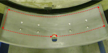
Figure 7. Semi-circle Caulk Application 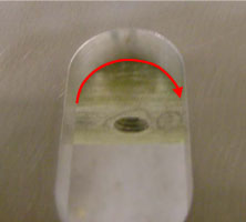
Figure 8. Front Edge Caulk Application 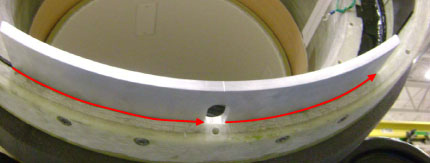
Figure 9. Left Edge Caulk Application 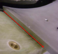
Figure 10. Back Edge Caulk Application (Apply caulk to the bottom edge where the BRM bracket and gradient surface meet) 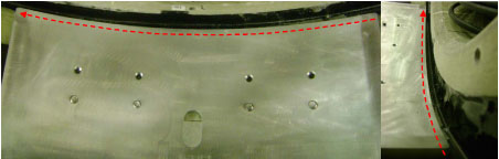
Figure 11. Right Edge Caulk Application 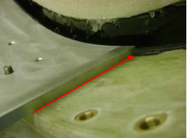
- Apply a small amount of caulk to the periphery of the threaded
bolts as shown in Figure 12. The process is the same whether 4 or 8 bolts
are used for the application.
Figure 12. Threaded Bolt Caulk Application 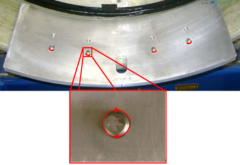
- Install rear support (2213167-3) to the rear of the gradient
in the same manner.Note:
There are 8 screws for each bracket. If the gradient has 8 holes, use 8 screws; if the gradient has 4 holes, use only 4 holes of the 8 holes on the bracket, as shown in Figure 13.
Note:The old brackets in the WideOpen Enclosure differ from the new brackets. See Figure 13.
Figure 13. Gradient Brackets Installation 
- Install the shipping blocks onto the defect Gradient coil cradle,
one on each end. See Figure 14.
Figure 14. Install Gradient Coil Shipping Blocks 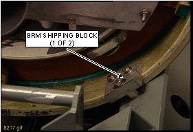 Note:
Note:Lift the defective Gradient coil and cradle from the cart using a fork lift or other lifting method that is capable of lifting 4000 lbs (1815 kg), and place on the ground. Lift the new Gradient Coil and cradle onto the cart using the same method.
- Clean the bolt threads by using a tack cloth to perform a back
forth motion clockwise/counterclockwise around the threads as shown
in Figure 2. Ensure any loose debris in the bolt threads is removed.
Finalization
No finalization steps.