Prerequisites
Table 1. Personnel requirements| Required persons | Preliminary requirements | Procedure | Finalization |
|---|
| 1 | Not Applicable | 1 hours | Not Applicable |
Table 2. Safety
| DANGER |
|---|
| FATAL ELECTRIC SHOCK HAZARD!! POSSIBLE +500 (1.0T) OR +1000 (1.5T) VOLT POTENTIAL TO THE
DYNAMIC DISABLE SWITCH BOARD. TO PREVENT POSSIBLE FATAL ELECTRIC SHOCK, DISCONNECT POWER
FROM THE RF Driver MODULE. |
| DANGER |
|---|
| FATAL ELECTRIC SHOCK HAZARD!! POSSIBLE +500 to 1000 VOLT POTENTIAL for 3.0T Systems TO
THE DYNAMIC DISABLE SWITCH BOARD. TO PREVENT POSSIBLE FATAL ELECTRIC SHOCK, DISCONNECT POWER
FROM THE RF Driver MODULE. |
|
About this task
Procedure for replacing Dynamic Disable Switch Boards.
Procedure
- Turn Driver Module Power off.
- Shut off power to the System cabinet by switching OFF the System
circuit breaker at the PDU.
- Lock out Tag out front panel cover at PDU. (Refer to OSHA Lockout Tagout Requirement.)
- Verify that power to the System Cabinet is off by checking the
fans and LEDs on the MGD Chassis, RRF Chassis and the Driver Module.
- Disconnect J72, J73, J75, and J76 at the Penetration Panel (magnet
enclosure side).
- Remove required magnet enclosures..
- Remove the covers from over the failed Dynamic Disable Switch
(DDS) board inside the magnet bore. See Figure 1 and Figure 2.
Figure 1. DYNAMIC DISABLE SWITCH BOARD REPLACEMENT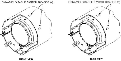 Figure 2. DYNAMIC DISABLE SWITCH BOARD LOCATION
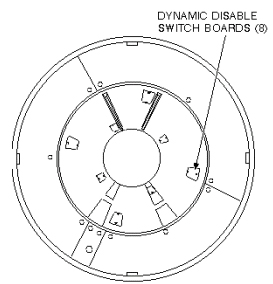
(Two of the boards are located under the bridge. Refer to procedure
for Bridge Removal/Replacement, for instructions on removing the bridge.)
- Remove Switch Board from Body Coil Assembly.
- See Installing Dynamic Disable Switch Board.
Finalization
No finalization steps.
