
- SIGNA MR355 / SIGNA MR360
- Service Manual
- 5856356-3EN Revision 5.0
- Basic Service Documentation. Copyright General Electric Company.
- 00000018WIA307E5F20GYZ
- id_131060201.7
- Jul 5, 2019 11:18:59 PM
Gradient Coil Installation Procedure
Prerequisites
| Required persons | Preliminary requirements | Procedure | Finalization |
|---|---|---|---|
| 3 | Not Applicable | 3-5 hours | Not Applicable |
| Item | Quantity | Effectivity | Part number | Manufacturer |
|---|---|---|---|---|
| Personal Protection Equipment | 1 | - | - | - |
| Gloves | 1 | - | - | - |
| Safety Glasses | 1 | - | - | - |
| Safety Shoes | 1 | - | - | - |
| Long Sleeve Shirts and Pants | 1 | - | - | - |
| Non-magnetic Tool Kit | 1 | - |
2385097 or 5112581 | - |
| Gradient Insertion Tool Kit | 1 | - |
2164744-5 or greater | - |
| BRM/BRM-D/CRM Cart | 1 | - |
2134810 | - |
| Aluminum Cradle | 1 | - |
2134810-2 | - |
| Cable Crimper/Stripper Kit | 1 | - |
2134776 | - |
| Poron Seal, for air cover | 1 | - |
2185175 | - |
| Poron Seal | 4 | - |
2181231 | - |
| Poron Seal | 8 | - |
2181231-2 | - |
| Splice kit | 1 | - |
2241521 | - |
| 5 Gallon Bucket to Collect Coolant | 1 | - |
2239133 | - |
| Authorized Personnel Floor Sign | 1 | - |
2289812 | - |
| Item | Quantity | Effectivity | Part number | Manufacturer |
|---|---|---|---|---|
| Bostic Brand Never-Seeze Compound | 1 | - |
46-294151P8 | - |
| Red Loctite # 271 | 1 | - |
46-170686p3 | - |
| Blue Loctite # 242 | 1 | - |
46-170684p2 | - |
| Ty-wraps | 5 | - |
- | - |
| Isopropyl Alcohol | 6 oz | - |
- | - |
| M10x30 Socket Hd Cap Screw, SS | 6 | - |
2109867-24 |
Fastenal |
| M10x30 Hx Hd Cap, SS (Can be Used Instead of M10x30 Socket Hd Cap Screw) | 6 | - |
2109866-21 |
Fastenal |
| Flat Washer SS, 10.5mm | 6 | - |
2184009 |
Fastenal |
| G10 Washer, 10.5mm | 6 | - |
2370892 | - |
| ||||||||||||
| Condition | Reference | Effectivity |
|---|---|---|
|
Perform the procedures listed in Pre-Requisite Procedures. | - | - |
Using Gradient Insertion Tool 2164744-6 or Greater
Procedure
- Note:Attach plates 5161983 and 5161985 to either the BRM or TRM gradient coil. Secure to gradient coil using M10 x 120 studs. Thread the studs at least 1/4 inch (6 mm) into the coil. The CRM gradient coil will have separate plates (part number 2187590, qty=2).
Changes have been made to the gradient insertion tool, part 2164744-6 and greater (such as 2164744-7). Use the parts noted below when replacing either BRM or TRM.
Figure 1. Gradient Mounting Plates 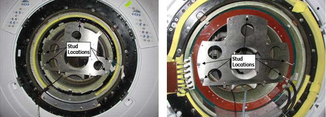
- Attach the rear plate to the magnet as shown below. There are
standoffs on this plate that should remain in place. Secure the rear
plate to the magnet using M10 x 80 studs, washers and M10 nut.
Figure 2. Attaching Rear Plate to Magnet 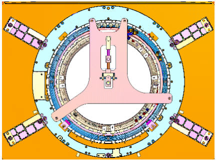
- Obtain the male insertion tube (2284929) and XRMB tube standoff
(5191626). Attach the tube standoff to the male insertion tube using
the 4 inch, 0.375-16UNC Hex Socket Screw (5303993) included in the
gradient coil insertion and lift kit. Once the standoff is secured
to the tube, attach the tube pilot shaft to the standoff.
Figure 3. Attaching Standoff to Insertion Tube 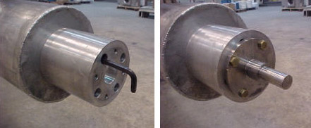
Gradient Coil Replacement
Procedure
- Install the cotter pin after the shaft is in place.
Figure 4. Cotter Pin Installation 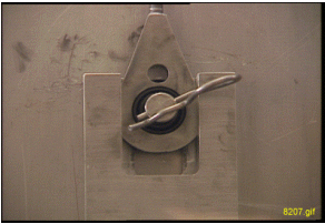
Extend cables as shown below.DANGER 
Figure 5. Routing of Cables 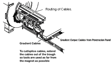 Note:
Note:The following illustration shows a typical cable routing for connection of the gradient output cables within an enclosed cable trough. If the site does not have enclosed cable trough, cables must be routed in serpentine manner and connected within rear pedestal.
Figure 6. Serpentine Cable Routing 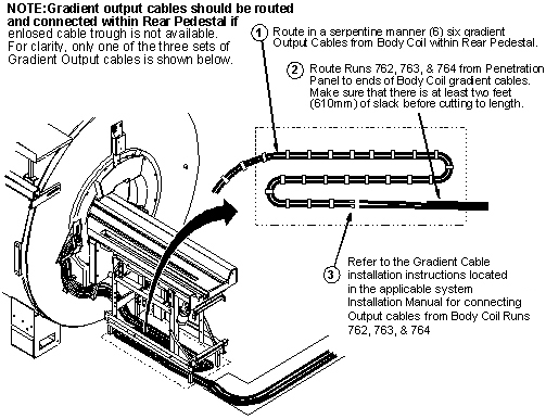
- Connect spliced cables. The gradient coil connections are as
follows:
X1 = X+ X2 = X- Y3 = Y+ Y4 = Y- Z5 = Z+ Z6 = Z- Figure 7. Cable Preparation 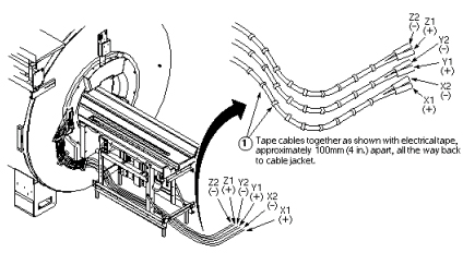
Figure 8. Connecting Spliced Cables 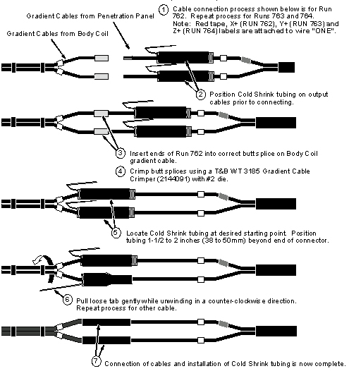
What to do next
Finalization
No finalization steps.