
- SIGNA MR355 / SIGNA MR360
- Service Manual
- 5856356-3EN Revision 5.0
- Basic Service Documentation. Copyright General Electric Company.
- 00000018WIA30DE5F20GYZ
- id_131065761.4
- Jul 6, 2019 12:17:30 AM
Replacing BRM RF Body Coil
Prerequisites
| Required persons | Preliminary requirements | Procedure | Finalization |
|---|---|---|---|
| 3 | Not Applicable | 3 to 5 hours | Not Applicable |
| Item | Quantity | Effectivity | Part number | Manufacturer |
|---|---|---|---|---|
| Personal Protection Equipment (PPE) | 1 set each | - | - | - |
| Protective Gloves | 1 pair each | - | - | - |
| Safety Glasses | 1 pair each | - | - | - |
| Safety Shoes | 1 pair each | - | - | - |
| Long Sleeve Shirt and Pants | 1 set each | - | - | - |
| Nonmagnetic Tool Kit | 1 | - |
46-320273G4 | - |
| 1 | - |
2164744-2 | - | |
| Authorized Personnel Floor Sign | 1 | - |
2289812 | - |
| Item | Quantity | Effectivity | Part number | Manufacturer |
|---|---|---|---|---|
| 1.5T HDx new color Short Body RF Coil - Yellow Black Case, ROHS version | 1 | - |
2208999-17 | - |
| ||||||||
| Condition | Reference | Effectivity |
|---|---|---|
|
Perform LOTO. See the MR Service Safety Manual, PN 5452735. | - | - |
|
For preliminary steps to the actual RF coil replacement for systems with a Cx or LCC magnet, refer to Defective Gradient Coil Removal. | - | - |
About this task
The RF body coil cartridge is a FRU that mounts inside the gradient coil (also a FRU), and is available in 1.0T and 1.5T versions. If the RF coil fails, it must be removed from the gradient coil and replaced with a new one. Since the replacement procedures for the RF and gradient coils are closely related, references are made below to the epoxy-filled gradient coil replacement procedure where the instructions for removal of like parts (for example, bridge removal) can be found. Although some tasks (such as connecting/disconnecting various cables, etc.) can be accomplished by one person, replacing a failed RF body coil requires three people.
Unpacking BRM RF Body Coil
About this task
A new RF body coil is packed in a cylindrical shipping container that is strapped inside a combination pallet and outer shipping box. It rests on a pair of installation tracks. The shipping container never leaves the box; the RF body coil is removed from this combination. Included are two extra installation tracks used in the gradient body coil to assist in the RF coil exchange.
Procedure
CAUTION
To perform all necessary steps for this part of the procedure, refer to each of the illustrations that follow.CAUTION Figure 1. Unpacking New BRM RF Body Coil 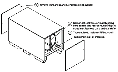
Figure 2. Separating BRM RF Body Coil from Shipping Container 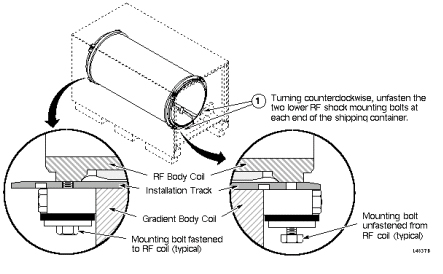
Figure 3. Shifting Installation Tracks in BRM Shipping Container 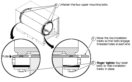
Figure 4. Removing BRM RF Body Coil from Shipping Container 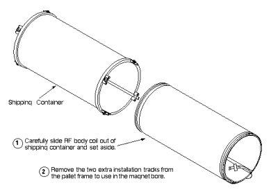
Figure 5. Placing Extra Installation Tracks Under BRM RF Coil 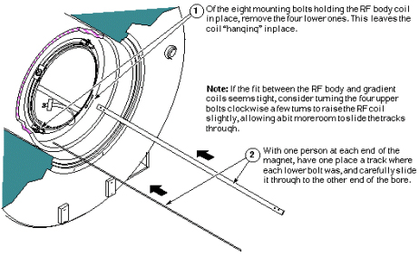
Figure 6. Attaching Tracks to Gradient Body Coil 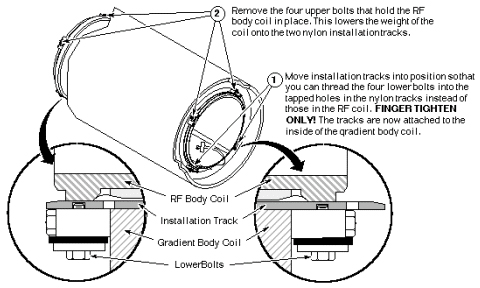
Figure 7. Sliding Out RF Body Coil onto Tracks 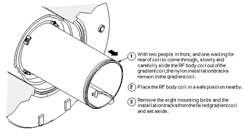
Figure 8. Sliding New RF Coil into Place 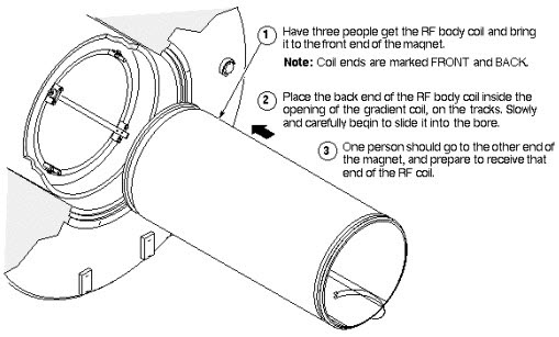
Figure 9. RF Coil Attachment and Track Removal 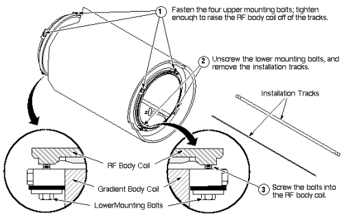
Figure 10. Centering BRM RF Coil in Gradient Coil 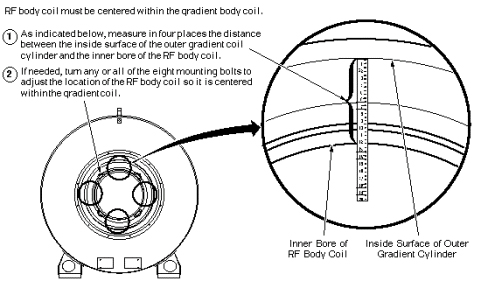
Preparing Failed BRM RF Body Coil for Shipment
Procedure
- Refer to the illustrations below for instructions on packing
the failed BRM RF body coil for shipment.
Figure 11. Loading Failed RF Coil into Shipping Container 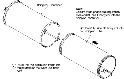
Figure 12. Fastening Installation Tracks to Shipping Container 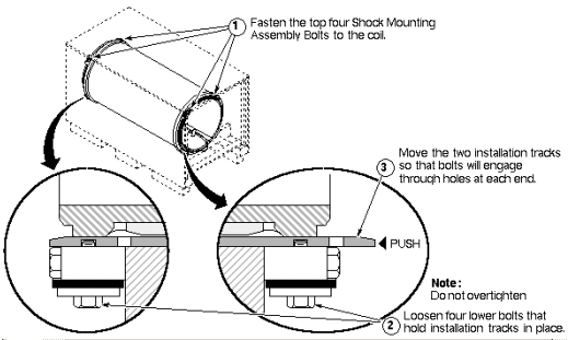
Figure 13. Securing BRM RF Coil in Shipping Container 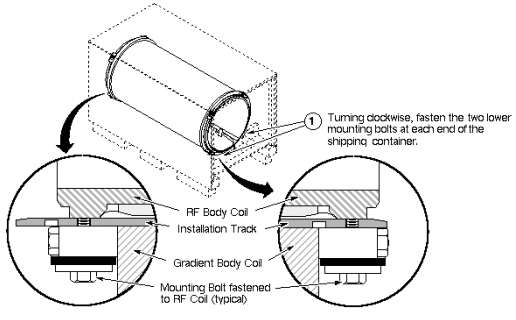
Figure 14. Closing BRM RF Shipping Container and Box 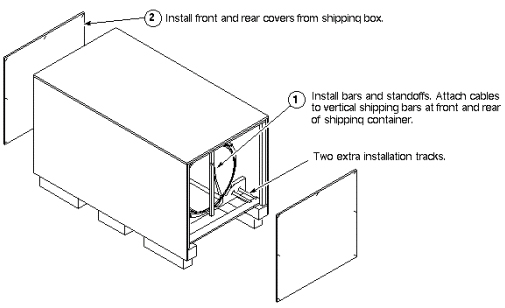
Finalization
Procedure
- Clean up the site in preparation for patient scans.
- Run head and body test scans to ensure proper operation.