
- SIGNA MR355 / SIGNA MR360
- Service Manual
- 5856356-3EN Revision 5.0
- Basic Service Documentation. Copyright General Electric Company.
- 00000018WIA308C1030GYZ
- id_131076421.3
- Jul 5, 2019 11:49:11 PM
Returning Plates to Gradient Insertion Tool Kit
Prerequisites
| Required persons | Preliminary requirements | Procedure | Finalization |
|---|---|---|---|
| 1 | - | - | - |
| Item | Quantity | Effectivity | Part number | Manufacturer |
|---|---|---|---|---|
| Alcohol | 1 | - | - | - |
| Ty-wraps | 5 | - | - | - |
| Non-Magnetic Tools | 1 each | - | 2385097 or 5112581 | - |
| Gradient Insertion Tool Kit | 1 | - |
2164744-2 | - |
| BRM/BRM-D/CRM Cart | 1 | - |
2134810 | - |
| Aluminum Cradle | 1 | - |
2134810-2 | - |
| Cable Crimper/Stripper Kit | 1 | - |
2134776 | - |
| Poron Seal, for air cover | 1 | - |
2185175 | - |
| Poron Seal | 4 | - |
2181231 | - |
| Poron Seal | 8 | - |
2181231-2 | - |
| Red Loctite # 271 | 1 | - |
46-170686p3 | - |
| Blue Loctite # 242 | 1 | - |
46-170684p2 | - |
| Splice kit | 1 | - |
2241521 | - |
| Condition | Reference | Effectivity |
|---|---|---|
|
Verify you have all the parts listed in Gradient Insertion Tool Kit Contents. | - | - |
|
Perform the procedures listed in Pre-Requisite Procedures. | - | - |
Procedure
- BRM plates with the rollers attached (spacers pointing up) are placed
in the crate. See Figure 1.
Figure 1. PLACEMENT OF BRM PLATES 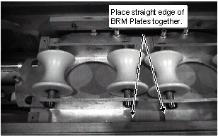
- Install threaded rod through spacer on the outer edge of the BRM plate
(see Figure 2) and secure with
washer and nut on bottom of BRM plate (see Figure 3).Note:
Slide threaded rod with washer and nut attached on end through the bottom of the spacer.
Figure 2. PLACEMENT OF BRM PLATES 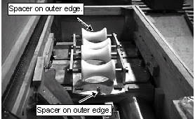
Figure 3. THREADED ROD AND SPACER ATTACHED TO BRM PLATE 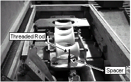
- Install CRM plates (labeled 55cm Plate) onto BRM plates and rollers
by placing CRM spacer on the threaded rod. See Figure 4.
Figure 4. PLACEMENT OF CRM PLATES 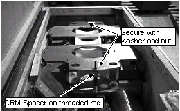
- Place BRM-D plate labeled Service End on CRM plates (see Figure 5). Line up holes on BRM-D plate and CRM
plates (see Figure 6).Note:
BRM-D Plate labeled Service End has the short spacers.
Figure 5. PLACEMENT OF BRM-D (SERVICE END) PLATE 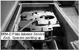
Figure 6. BRM-D PLATE ALIGNMENT 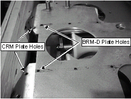
- Underneath the CRM plates slide the threaded rods through the aligned
holes of the CRM and BRM-D plates. See Figure 7.
Figure 7. PLACEMENT OF THREADED RODS IN CRM & BRM-D PLATES 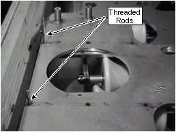 Note:
Note:Allow the threaded rods to rest on the BRM plates while performing next step.
- Place the BRM-D plate, labeled Patient End, on top of the Service End
BRM-D plate. Threaded rods will go through the same holes as on the Service
End BRM-D plate. See Figure 8.
Figure 8. PLACEMENT OF THE PATIENT END BRM-D PLATE 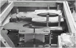
Finalization
No finalization steps.