- id_2002119
- Version: 5.9
- Date: Jan 28, 2020 1:23:24 PM
Running ICW Installation mode
The Installation and Calibration Wizard provides an interface to navigate through required system procedures, checks and calibrations.
Prerequisites
| Personnel requirements | |||
|---|---|---|---|
| Required persons | Preliminary requirements | Procedure | Finalization |
| 1 | - | Varies | - |
| Required conditions |
|---|
| Make sure all customer-purchased options are installed before running ICW. Any options added after running ICW will not be displayed. |
| A service key is required to launch the Installation and Calibration Wizard. |
Figure 1. ICW Install mode screen
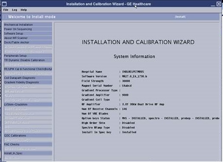
- The left pane lists all tasks required to complete the installation.
- Tasks must generally be completed in order, from top to bottom (tasks with prerequisites are grayed out until all prerequisites are completed). Non-grayed out tasks may be completed in any order or in parallel.
- After a task is completed, click Check Status in the right pane. Completed tasks turn blue; failed tasks turn red.
- ICW remains in installation mode until all tasks are successfully completed.
Figure 2. ICW calibration tool interface
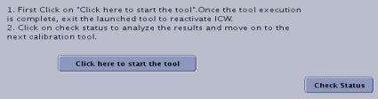
When running these tools within ICW, some of the finalization tasks such as Doing a TPS reset or Saving information will be automatically completed by ICW.
Procedure
- Before opening ICW for the first time, make sure all options purchased by the customer are installed. note:
The option key check is only done the first time the tool is used. Any change to the option key status after ICW has started will not be displayed.
- From the Common Service Desktop select .
- Use the following tables as a reference to identify what tasks are needed to complete each procedure within ICW.note: Relaunching a completed task in ICW displays a dialog showing prerequisite tasks. You may want to rerun the prerequisites listed before rerunning the selected task.
Table 1 ICW checks and procedures Procedure Tasks Power On Sequencing Acknowledge that the following tasks have been completed: - Is the HEC transformer switch in spec?
- Have you filled chiller and lines with coolant and removed the mdp jumper? (HEC Coolant Fill and Coolant Leak Check)
- Is magnet monitor power connected to customer source?
- Is the incoming power wiring to the PDU in spec?
- Are coolant leak checks done? (HEC Coolant Fill and Coolant Leak Check)
See Power On Sequencing.
Software Setup note: If the system is staged with enhanced GOC, do not load software.Load host system software (if required).
Answer the following questions on the screen and submit:
- Has the GOC come with software pre-loaded? (Yes/No)
- Does the system have the latest service pack software loaded? (Installing Service Packs)
- Have you loaded the customer Operator's Manual? (Loading Operator Documentation)
- Make sure the system parameters (hardware and software) are correct so that the information can be verified in About MR Scanner.
- Have you rebooted the system?
About MR Scanner Display Scanner Information.
See Running the About MR Scanner tool.Dock/Table Anchor See Dock Adjustments.- Is dock anchor installation compliance with Preinstallation Manual (PIM) checked (two-part anchor, allowing dock to slide forward without being lifted)?
- Is dock centering completed?
Magnet Ramping and Shimming Refer to the applicable Magnet and Cryogens subsystem manual for the specific procedures required for these items.- Checking off ICW Magnet Ramping items
- Magnet pre-ramp requirements completed: Ramping Magnet to Field
- Magnet rundown unit functional check completed: Magnet Rundown Unit (MRU) Checks
- Magnet ramping completed: Ramping Magnet to Field
- Magnet shimming prerequisites completed
- Initial shim current installation complete
- Passive shim completed: Shimming
Table Installation/Adjustments note: All adjustments are iterative. If one adjustment is made, make sure that other adjustments have not been compromised. Measurements must be entered in the ICW dialog.See Patient Handling Adjustments.
With the release of DV25, actual measurements must be entered in the ICW dialog. Click on the Help option to the right of the task to bring up the associated service documentation.
- Follow the table adjustment process as it is presented in the ICW dialog. Enter measurement data where it applies. Click on the Help option to the right of the task to bring up the associated service documentation.
- For systems with multiple tables: Is Dual Table Alignment completed?
Peripherals Setup - Body coil air flow functional checks completed: Body Coil Air Flow Functional Check
- Laser light aligned: Laser Light Alignment
- In-room monitor and software installednote:
In-room monitor is an option. If no in-room monitor is installed, this check box must still be checked to complete the step.
Table 2 ICW calibration procedures Procedure Tasks TR Dynamic Disable Calibration RF/UPM Cal & Functional Check (Body) RF/UPM Cal & Functional Check (Head)
See Body and Head Maximum Power Setup and Calibration. Coil Datapath Diagnostic See Doing the coil datapath diagnostic. Gradient Fidelity Diagnostic See Gradient Fidelity Diagnostic. DQA (Image Orientation) See Doing DQA calibration EPI White Pixel See Doing the EPI white pixel test (PM mode). LVShim Rough (G3 only) See LVShim Procedures. Grafidy Grafidy Eddy Current Calibration
See Calibrating grafidy.LVShim Main - Shim To Spec, Supercon: LVShim Procedures Gradient/Iso Vector Z Calibration (DQA II Tool) LVShim Gradshim See Running LVShim Gradshim. HOEC note: The same calibration hardware setup used for LVShim is used for HOEC.HOS Calibration note: The same calibration hardware setup used for LVShim is used for HOEC.For systems with HOS option: See HOShim Cal Ref Map Creation Procedures and Verification.
HOS Calibration note: The same calibration hardware setup used for LVShim is used for HOEC.Functional Check: High Order Shim Functional Check .
System Gain Calibration System Gain Calibration (Head and Body): System gain calibration B0 Drift Calibration See B0 Drift Calibration.
SPT Full Test Mode System Performance Test (SPT): Full Test Mode
EPT Echo Planar Test (EPT)
Probe Tuning & SNR Check See Probe Tuning and SNR Check Tool (DV24 and later). GOC Calibrations Complete the following tasks and acknowledge: - Intercom adjustments
- PACS & HIS/RIS configuration
- Pneumatic patient alert checks
Coil SNR Tests/MCQA - For each coil the customer has purchased, perform necessary installation steps and run the appropriate SNR or MCQA test. See 1.5T Coil Vendor Manuals for the test procedures.
- Confirm that each coil the customer has purchased has been plugged into the scanner at least once.
note: When building a protocol, only commonly purchased coils are shown by default. When a coil is plugged in for the first time, the system automatically shows the coil. If the customer wants to hide one of the commonly purchased coils because they did not purchase the coil, use the “hide” coil function available in the Coil Packages tab of Coil Database Explorer.PAC Checks - Peripheral pulse probe checked
- ECG leads checked
- Respiratory compensation checked
See ICW PAC Checks.
Install In Spec Generating the System in Spec (IIS) Authentication Key
Click Click here to start the tool. If failures are observed, perform necessary cals, repeat check, and click Check Status once passed.note: After clicking Check Status, a SaveInfo prompt is displayed (if all preceding steps have been successfully completed). Perform a SaveInfo. (See Saving information)Table 3 ICW finalization procedures Procedure Tasks Finalization ICW Finalization
- InSite checkout completed: InSite/IIP
- Magnet pressure control functional check
- Magnet monitor checkout
- Planned maintenance initialization
- SaveInfo performed
- Product locator data entered into GIB
- Applicable Service Licenses generated and installed on system (see Service licensing)