- id_13107370
- Version: 3.0
- Date: Aug 29, 2019 1:29:31 AM
Power On Sequencing
Prerequisites
| Required persons | Preliminary requirements | Procedure | Finalization |
|---|---|---|---|
| 1 | Not Applicable | 15-60 minutes | Not Applicable |
| Item | Quantity | Effectivity | Part number | Manufacturer |
|---|---|---|---|---|
| Digital Volt Meter (DVM) | 1 | - | - | - |
|


Figure 1. Power Flow Block Diagram
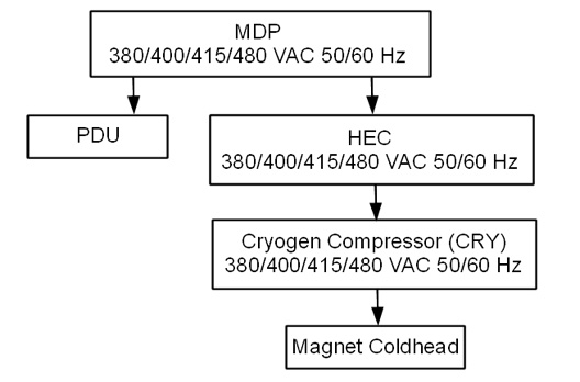
Main Components
The following provides an overview of each main component in this sequence:
-
Main Disconnect Panel (MDP)
The MDP contains a control power transformer that is manufactured by either GE or TEAL. It is set to 480 Vac by default. For sites with a different customer-supplied voltage, the control power transformer wiring will need to be changed. The MDP also contains a temporary jumper used to power up the system. That jumper will need to be removed. See Figure 4 and Table 5 for more details. The temporary jumper is used until the remote Emergency Off buttons are installed.
-
Heat Exchange Cabinet (HEC)
The HEC contains a control power transformer that is set to 480 Vac. For sites with a different customer-supplied voltage, the control power transformer wiring switch will need to be changed. The HEC contains the power interface to the Cryogen Cooler Compressor (CRY). In order to power the coldhead after magnet delivery, the power cabling will need to be wired from the MDP to the HEC, and from the HEC to the Cryo Cooler. The power cable between the MDP and the HEC will be customer supplied and installed.
-
Cryogen Cooler Compressor (CRY)
The CRY receives power from the HEC. The coldhead power cable will need to be installed to power the coldhead.
-
Power Distribution Unit (PDU)
The PDU is setup for 480 Vac by default. For sites with a different customer supplied voltage, the power wiring will need to be changed. The power cable between the MDP and the PDU will be customer supplied and installed. The overload and short-circuit settings are dependent upon the voltage input and may need to be changed if the input voltage is changed. Not all PDUs need overload and short circuit current settings adjusted. Refer to installed PDU's manual to determine adjustment requirements.
-
Power & Gradient Cabinet (PGR)
The PGR houses the eXtreme Gradient Amplifiers (XGA or XG2), eXtreme Power Supplies (XPS or XPS2) and the PDU. The gradient cable connections to the XGA or XG2 for each axis can be accessed here.
List of Procedures
This document includes the following Power On Checklist procedures:
-
Confirm the Main Disconnect Panel (MDP) Voltage Selection
-
Confirm the Main Disconnect Panel (MDP) Jumper Interlock has been removed
-
Confirm the Heat Exchange Cabinet (HEC) Voltage Selection
-
Confirm Internal Power Wiring to the Power Distribution Unit (PDU)
-
Confirm Overload and Short Circuit Trip Settings for the PDU Input Circuit Breaker (Pre-DVapps PDU 5140621)
-
Check the gradient cable connection at the PGR
Confirm the Main Disconnect Panel (MDP) Voltage Selection
The Main Disconnect Panel is shipped with the default voltage setting of 480 Vac.
Procedure
- Confirm that the control power transformer connections are in
the correct configuration for your site.
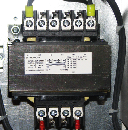
Table 4 Control Power Transformer Connection Configuration Incoming Voltage: GE Transformer Terminal: TEAL Transformer Terminal 380 VAC H3 H4 400 VAC H3 H5 415 VAC H3 H5 480 VAC H4 H6 - If the power connections are not configured properly, have the
proper personnel correct the wiring. See MDP Operation and
Maintenance Manual for additional details.
Figure 2. GE MDP Control Power Transformer (H4 Input Wiring Shown)
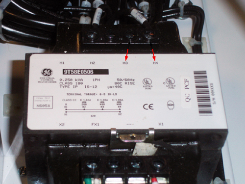
Figure 3. TEAL MDP Control Power Transformer
Confirm Main Disconnect Panel (MDP) Jumper Interlock Has Been Removed
The Main Disconnect Panel is shipped with the E-off jumper installed.
Procedure
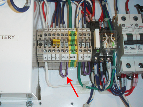
- Confirm that the E-off jumper(s) have/has been removed. Remote
E-off push buttons replace the jumper(s).
Table 5 Location of E-Off Jumper(s) MDP Manufacturer MDP Jumper Terminals GE 15 and 16
TEAL 15 and 19
16 and 19
- If the jumper is not removed, have the proper personnel correct
the wiring. See MDP Operation and Maintenance Manual for additional details.
Figure 4. MDP Terminal Board with Jumpers Installed (GE MDP Shown)
Confirm Heat Exchange Cabinet (HEC) Voltage Selection
Procedure
- Follow the table below to confirm the transformer switch is
in the proper position. See Figure 5.
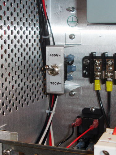
Table 6 Transformer Switch Position Incoming Voltage HEC Switch Position 480, 415, or 400 Vac Up 380 Vac Down note:The UP position is labelled "480V~" and the DOWN position is labelled "380V~".
- If the switch is not in the correct position, change the switch
position.
Figure 5. HEC Voltage Selection Switch
Confirm Internal Power Wiring to the Power Distribution Unit (PDU)
The PDU is shipped with the default voltage setting of 480 Vac.
Procedure
- Remove the small cover plate which is held in place by two screws.
Figure 6. Input Voltage Select Small Cover (79 kVA)
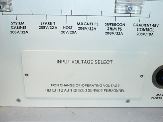
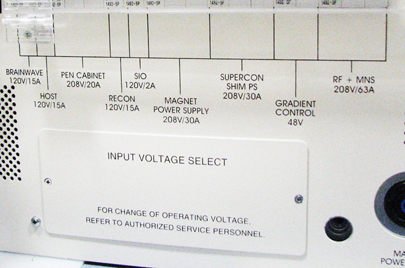
Figure 7. Input Voltage Select Small Cover (73 kVA)
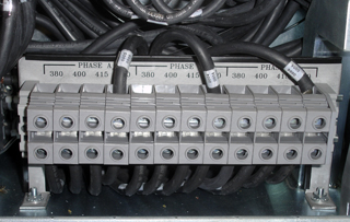
- Confirm that the three Input Voltage Selection Terminal Blocks
are wired in the correct configuration. If the power connections are
not configured properly, ensure that the proper personnel correct
the wiring. See PDU Operation and Maintenance Manual for additional details.
Figure 8. Input Voltage Selection - Set at 480 Vac
Confirm Overload and Short Circuit Trip Settings for the PDU Input Circuit Breaker
Note: Overload and Short Circuit Trip Settings only apply to pre-DVapps PDU 5140621. The overload and short circuit trip settings for the Input Circuit Breaker must be set to the correct values corresponding to the input voltage.
Procedure
- Remove the small cover plate under the main circuit breaker.
- Lift open the transparent plastic cover on the lower portion of the circuit breaker to access the DIP switches controlling the circuit breaker.
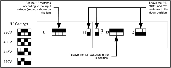
- Confirm that the switches immediately under the letter “L”
are configured correctly. The illustration below shows the position
of the DIP switches for each input voltage.
Figure 9. Circuit Breaker DIP Switch Settings (Black=ON / White=OFF)
- If the DIP switches are not configured correctly, ensure that proper personnel correct the DIP switches settings per the PDU Operation and Maintenance Manual
Check Gradient Cable Connection at PGR
Procedure
- Check the gradient cable connections at the PGR to confirm no
shorts between two axis or load shorts to ground.note:
Complete this section BEFORE applying power to the PGR.
- Ensure the following checks between points are low resistance
(< 5 ohms) with a DVM in the following table.
Table 7 PGR Gradient Coil Load Check — Ensure Same Coil From To Expected Value X-Axis XGA(XG2) – J17 X-Axis XGA(XG2) – J18 < 5 ohms Y-Axis XGA(XG2) – J17 Y-Axis XGA(XG2) – J18 < 5 ohms Z-Axis XGA(XG2) – J17 Z-Axis XGA(XG2) – J18 < 5 ohms - Ensure the following checks between points are open (> 10 k
ohms) with a DVM in the following table.
Table 8 PGR Gradient Coil Load Check — No Shorts From To Expected Value X-Axis XGA(XG2) – J17 Y-Axis XGA(XG2) – J17 > 10 k ohms X-Axis XGA(XG2) – J17 Z-Axis XGA(XG2) – J17 > 10 k ohms Y-Axis XGA(XG2) – J17 Z-Axis XGA(XG2) – J17 > 10 k ohms X-Axis XGA(XG2) – J17 Ground > 10 k ohms Y-Axis XGA(XG2) – J17 Ground > 10 k ohms Z-Axis XGA(XG2) – J17 Ground > 10 k ohms - If any of the Table 4 and Table 5 checks fail, review the installation
instructions for gradient cable connections between the magnet and
the PGR prior to applying power to the system. note:
This check does not ensure X, Y and Z gradient load coils are connected to the corresponding gradient amplifier.
Finalization
Finalization
Select Installation Calibration Wizard checklist items that were confirmed as completed.