- id_13106486
- Version: 3.1
- Date: Nov 3, 2019 10:01:06 PM
HEC Hose Inspection, Coolant Fill, and Coolant Leak Check
Prerequisites
| Required persons | Preliminary requirements | Procedure | Finalization |
|---|---|---|---|
| 1 | Not Applicable | 90 minutes | Not Applicable |
| Item | Quantity | Effectivity | Part number | Manufacturer |
|---|---|---|---|---|
| 5 gallon pail | 1 | - | - | - |
| Item | Quantity | Effectivity | Part number | Manufacturer |
|---|---|---|---|---|
| Coolant | As required (48 one-gallon containers shipped with the system) | - |
5174313 |
- |
| Paper towels (white) | 1 roll | - | - | - |
| Teflon (PTFE) tape | As required | - | - | - |
|


| Condition | Reference | Effectivity |
|---|---|---|
|
Shutoff (ball) valves are open. |
- | - |
|
Hose connections are secure. |
- | - |
|
Check valves are correctly oriented. |
- | - |
This procedure provides instruction to properly:
-
Inspect the hoses and valves to ensure that they are correctly installed.
-
Fill the gradient coil and power electronics tanks in the Heat Exchange Cabinet (HEC) with a deionized water solution. (Usually, the gradient coil tank is filled before the power electronics tank.)
-
Check the valves for leaks after the pumps are activated and the fluid is circulating.
Hose and Valve Check
Procedure
- Ensure the hose connections are secure from the HEC to the PGR cabinet, and from the HEC to the gradient coil.
- Verify ball (shutoff) and check valve connections to ensure they are tightened properly. (If either can be hand tightened, they are too loose.)
- Inspect the orientation of the check valves in the blue, black, green, and red hoses.
Orientation should be per the schematic in Figure 1. The check valves in the supply hoses to the PGR cabinet (green) and the gradient coil (blue) should have the flow arrow pointing away from the HEC. The check valves in the return hoses from the PGR cabinet (red) and the gradient coil (black) should have the flow arrow pointing towards the HEC.
If any valve is reversed, do not proceed with the procedure until the check valve is properly installed.
Figure 1. HEC Coolant Schematic
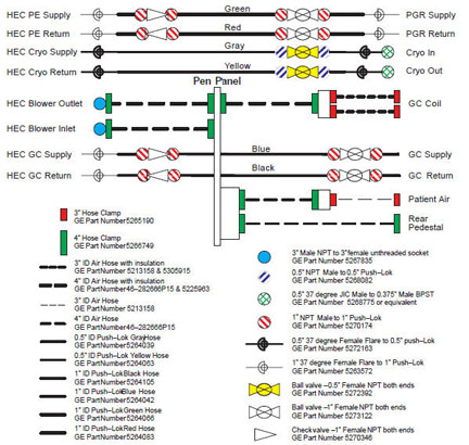
To view a high-resolution image of this schematic, , available from the online documentation library.
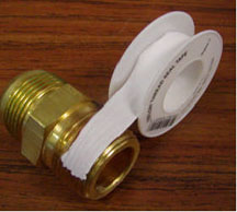
- Make sure the Teflon tape is applied properly as shown in Figure 3.
- If there is an issue with any of the connections, retighten or reapply new Teflon tape as needed before adding any coolant to the system.
- To apply new Teflon tape, start one thread in from the end of the male NPT fitting. Doing so will prevent tape from entering the fluid passage.
Figure 2. Applying New Teflon Tape
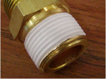
- Because Teflon tape is not adhesive-backed, hold the end of the tape with a finger until one full wrap is completed. Wind the tape in a clockwise direction (as viewed from the end of the fitting). This ensures that the installation of the mating components results in wrapping the tape in the same direction and not unraveling or unwinding it.
Figure 3. Correct Application of Teflon Tape
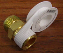
- After the first wrap, continue wrapping in a clockwise direction with moderate tension applied to the tape roll. Overlap the prior layer by a half width of the tape as shown in Figure 4. This ensures that two layers of tape cover all threads of the fitting.
Figure 4. Teflon Tape Overlap
- To apply new Teflon tape, start one thread in from the end of the male NPT fitting. Doing so will prevent tape from entering the fluid passage.
Coolant Fill
Procedure
- All shutoff valves must be open before the tanks can be filled with coolant. See Figure 1 for valve locations.
-
A shutoff valve is open when the valve handle is parallel to the hose as shown in Figure 5.
-
A shutoff valve is closed when the valve handle is perpendicular to the hose.
-
The gate valve beneath each tank in the HEC needs to be fully open (handle rotated counterclockwise until it stops).
Figure 5. Shutoff (Ball) Valves
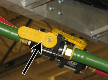 note: The shutoff valves in this illustration are shown open (handle parallel to hose). When the handle is perpendicular to the hose, the valve is closed.
 -
- For each of the valves (ball and check), wrap the white paper towel around the entire joint, and tape it securely to the hose. Be sure to use white paper towels. (This helps distinguish between a leak, indicated by a blue liquid, and condensation, a clear liquid.)
- Unscrew the cap from the top of the tank.
- Insert the tank funnel extension and funnel into the opening on top of the tank.
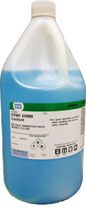
Figure 6. One Coolant Gallon
 note: The coolant fluid is dyed for easy detection of leaks. This also helps distinguish between a leak and any normal condensation on the hoses.
 - Pour the coolant into the funnel to fill the tank. Fill the tank slightly more than 6 inches above the warning sensor. Watch the PE or GC display on the HEC controller to see when the tank is full.
Figure 7. Filling Coolant Tank
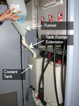
Figure 8. Coolant Level
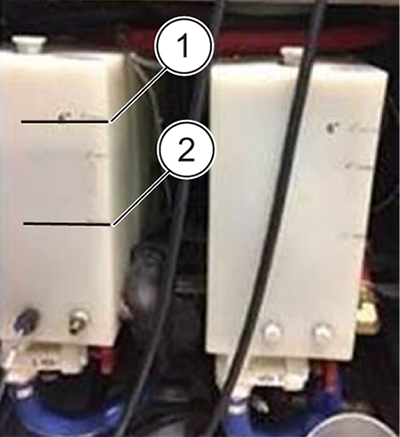
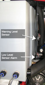
ITEM DESCRIPTION 1 6 inches from top coolant level sensor 2 Level of top coolant level sensor There are two sensors on the right side of each tank. The top sensor is a warning level sensor that notifies the operator when the coolant is low. The lower sensor on the right of the tank is a low level alarm that signals the operator when the coolant reaches a dangerously low level and the system will stop scanning.
Figure 9. Coolant Sensors
- notice
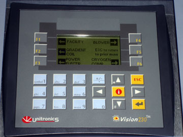
- For each tank, press and hold the up arrow ▲, while pressing the appropriate function key (shown in the table) on the HEC pump control panel. (This sequence activates the pump to fill the hoses with coolant and turns the pump on and off.)
Table 6 Pump Control Panel Key Sequence Tank Key Sequence Gradient coil ▲ F2 Power electronics ▲ F3 These key sequence turn on the respective pumps. The variable frequency drives ramp the pumps up to operating speed slowly. Air is displaced in the system during initial pump power-on, so the level of the coolant is expected to go down. If the pump shuts itself off, the air escaping the system may have falsely tripped a level sensor. Continue pressing the respective key sequence and adding coolant until the pump reaches a stable operating speed and remains running.
Figure 10. HEC Control Panel
- Repeat Step 3 through Step 6 until the next tank level is stabilized, about 4-5 inches from the top of the tank, signifying the cooling loop is completely filled with coolant.
- Screw the cap onto the top of the coolant tank.
- Turn on the pumps using the key sequence described in Step 6, and allow the system to run for 30 minutes.
- Proceed to the next section, Coolant Leak Check.
 |
Coolant Leak Check
Procedure
- After the system runs for about 30 minutes, check each of the paper towels for evidence of a coolant leak.note: A coolant leak shows as blue. Normal condensation is clear.
- notice
- If a leak is found, turn off the pumps at the bottom of the HEC. For each tank, hold down the keys (shown in Table 6) simultaneously on the HEC control panel. This sequence toggles the pumps on and off.
- Proceed to Coolant Leak Troubleshooting.
|
Coolant Leak Troubleshooting
If a leak is found in one or more of the valves, review the following steps:
Procedure
-
Problem: Teflon tape is applied incorrectly (not consistently covering threads, or torn).
Solution: Remove existing Teflon tape. To access the check or ball valve with faulty Teflon tape, see Draining Guidelines for Hoses External to HEC. Replace the tape on the valve by following Step 5.a through Step 5.c.
-
Problem: Valve connection is improperly tightened. This can be caused if the connection is too loose or the connection is overtightened (causing a fitting to break).
Solution: If the connection seems to be loose, hand tighten the fittings, and then turn the wrench three turns. (Do not overtighten, and make sure the leak stops.)
-
Inspect the valve for damage and replace as necessary.
-
If a replacement is required, refer to Draining Guidelines for Hoses External to HEC before disconnecting any valves.
-
- After the issue is properly resolved, ensure the coolant system is functioning properly.
- Fill the system with coolant as specified in Coolant Fill.
- Turn on the pump drives from the HEC control panel, using the keys in Table 6 for the appropriate commands.
- Check for leaks at all hose connections, especially the connection just repaired. (See Figure 1 for connection locations.)
Draining Guidelines for Hoses External to HEC
Perform LOTO on the HEC. See the MR Service Safety Manual, PN 5452735.
PGR or Gradient Coil Lines with Check Valves
This section contains draining techniques when troubleshooting a leak at the check valve (P/N 5270346).
Procedure
- Isolate PGR or gradient coil lines by shutting off both the supply and return 1 inch ball valves (P/N 5273122). Locations are shown in Figure 1. The maximum volume can be calculated with the following equation:
Maximum volume of fluid in 1 inch hose = (0.507 x L) liters, where L = length of hose in meters and 1 gallon = 3.78 liters.
- Lift the hose with the check valve to drain as much fluid as possible back into the HEC.
- notice
- Unthread the leaking side of the check valve from the fitting, and drain the fluid into the pail.
|
PGR or Gradient Coil Lines with Ball Valves
This section contains draining techniques when troubleshooting a leak at the ball valves (P/N 5272392).
Procedure
- Isolate PGR or Gradient Coil lines by shutting off both the supply and return ball valves (P/N 5273122). Refer to Figure 1 for the ball valve locations.
- Kink the appropriate hose to isolate the fluid. If kinking is not enough to hold the volume of fluid between the ball valve and the source, drain into a pail or the gradient coil.
- Use a pail to drain the fluid between the check and ball valves. The maximum volume can be calculated with the following equation:
Maximum volume of fluid in 1 inch hose = (0.507 x L) liters, where L = length of hose in meters and 1 gallon = 3.78 liters.
- Lift the hose with the ball valve to drain as much fluid as possible.
- Unthread the leaking side of the ball valve from the fitting.
Cryogen Compressor Lines with Ball Valves
This section contains draining techniques when troubleshooting a leak at the ball valve (P/N 5272392).
Procedure
- Isolate the cryogen compressor lines by shutting off both the facility supply and return 1/2 inch ball valves contained within the HEC.
- Kink the appropriate hose to isolate the fluid. If kinking is not enough to hold the volume of fluid between the ball valve and the source, use a pail to drain the fluid. The maximum volume can be calculated with the following equation:
Maximum volume of fluid in 0.5 inch hose (cryogen compressor) = (0.12272 x L) liters, where L = length of hose in meters and 1 gallon = 3.78 liters.
- Lift the hose with the ball valve to drain as much fluid as possible.
- Unthread the leaking side of the ball valve from the fitting.
Finalization
Procedure
- When finished filling the tanks with coolant, place the funnel and tank funnel extension at the bottom of the HEC.
- Keep any unused coolant for future use.
- After the procedure is completed, view the hose connections closely to check for any leaks.
- Check the hoses a second time after a few days (during installation) for any possible leaks.