- id_13107520
- Version: 3.0
- Date: Aug 29, 2019 1:31:52 AM
High Order Eddy Current (HOEC) Calibration
Prerequisites
| Required persons | Preliminary requirements | Procedure | Finalization |
|---|---|---|---|
| 1 | Not Applicable | 60 minutes | 10 minutes |
|


| Condition | Reference | Effectivity |
|---|---|---|
|
Confirm that Grafidy Eddy Current Calibration is complete |
- | |
|
Remove all coils from the cradle and phantoms from the bore. |
- | - |
Use the High Order Eddy Current (HOEC) procedure to characterize the time dependent magnetic field errors in the bore up to at least the third order. This calibration works in conjunction with Grafidy Eddy Current Calibration, which adjusts and compensates the short, long, and very long time constant eddy currents for both linear and B0 terms. Run the HOEC calibration anytime after Grafidy is run.
Preparing for HOEC Procedure
Procedure
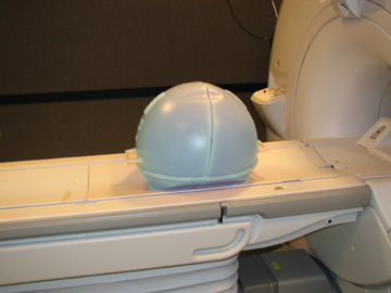
- Set up and align the LVShim phantom. Align the phantom so that:
-
The phantom’s seam is oriented perpendicular to the table.
-
The phantom’s z-axis is along the length of the cradle.
-
The phantom is centered left to right with respect to the cradle top.
Figure 1. Place Phantom on Patient Table
-
- Landmark on the LVShim phantom crosshairs.
- Press the Advance to Scan button.
- Start the HOEC tool from the Common Service Desktop, on the
Calibration tab.
Select Calibration > HOEC Calibration, and then select Click here to start this tool.
Running HOEC
Procedure
- Confirm that all three axis are selected (screen default) Figure 2.
- In the HOEC window, select Scan.
- In the status window, the tool displays the message that the
analysis is complete for each axis (x, y, and z).
If the tool completed the analysis for all three axes, exit the tool. If the tool did not complete the analysis, review the error log for possible system issues.
Figure 2. HOEC with Results
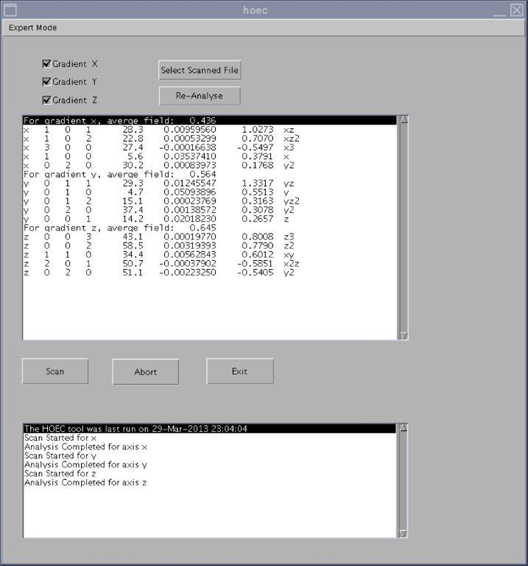
This control: Does this: Expert Mode button Allows you to view the images analyzed by the tool. (This is primarily used to look for sources of error.) Use Expert Mode only if directed to do so by OLC. Gradient X/Y/Z boxes By default, all three of these boxes are checked. When one of these boxes is checked, that gradient is included in the HOEC calibration. Select Scanned File button Click this button to select the results file from a previous HOEC calibration. Re-Analyse button Click this button to reanalyze the results file from a previous HOEC calibration. You must select a scanned file before clicking this button. Scan button Starts the HOEC calibration. Abort button Stops the HOEC calibration. Exit button Closes the HOEC calibration tool.
Finalization
Procedure
- Remove any phantoms from the bore.
- Perform SaveInfo.
- Perform Doing a check scan before turning the system over to the customer.