- id_13106527
- Version: 3.0
- Date: Aug 29, 2019 1:41:41 AM
HOShim Reference Map Creation and Verification
Prerequisites
| Required persons | Preliminary requirements | Procedure | Finalization |
|---|---|---|---|
| 1 | Not Applicable | 90 minutes | Not Applicable |
| Item | Quantity | Effectivity | Part number | Manufacturer |
|---|---|---|---|---|
| LVShim Phantom Assembly | 1 | - | - | - |
|

| Condition | Reference | Effectivity |
|---|---|---|
|
DQA calibration, Grafidy, LVShim, RF output adjustment, and UPM calibration (head and body) must be completed before running this procedure. |
- | - |
|
Software must be fully operational. |
- | - |
|
Gradient calibration must be within specification. |
- | - |
|
No image artifacts can be present. |
- | - |
High Order Shim (HOShim) Reference Map Creation uses the same phantom setup and protocol as LVShim.
Field Map Creation
Procedure
- At the Operator Workstation, select Service Desktop and prepare the system by performing a TPS Reset.
- notice
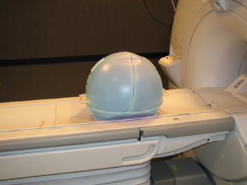
- Set up and align the LVShim phantom.note:
For DV systems earlier than 22.x, 1.5T uses green phantoms and 3.0T uses pink phantoms.
For DV systems 23.x and later, 1.5T uses green phantoms and 3.0T uses either green or pink phantoms.
Figure 1. Placing LVShim Phantom on Patient Table
- Landmark on the LVShim phantom crosshairs.
- Press the Advance to Scan button.
- Perform a phantom centering check scan and center frequency check using manual prescan, and then click Save Frequency.
- At the Operator Workstation, select the scan icon from the desktop
control panel and set up the High Order Shim calibration scan as follows.
-
Click the New Worklist icon.
-
Patient ID: geservice
-
Name: HOS Cal
-
Weight (lb.): 300
-
- Under Patient Protocols, select Service, and click Other.
- Find and select the LVShim protocol, and click 1 for Series.
- Click Accept to download the series.
- Click Save.
- To execute the scan, select Start Exam > Save Rx > Scan.
- When the image displays in the Autoview window, select the Series Data tab. Select Exam > Series > Image, and click Viewer.
- Verify that the phantom is centered in the Z axis:
- Click User Prefs.
- In the User Preferences pop-up window, find Grid Prefs and click Customize.
- Change Grid Spacing (mm) to 150, and click OK then Apply.
- Select the Grid Symbol button to turn
on the grid.
Figure 2. Centering LV Phantom (Alignment Grid)
- Adjust the W (Window) and L (Level) settings until the edges of the phantom image can be clearly seen.
- Verify that the inner phantom sphere is centered within the 150 mm grid in the S/I direction. If the phantom is not centered, move the phantom in or out of the bore and right to left as necessary, based on the grid markings. If the phantom is not centered, move the phantom in or out of the bore and right to left as necessary (based on the grid markings), then landmark again and re-scan.
 |
Running Makereference Script
The Makereference script takes 45 minutes to complete.
Procedure
- Start the HOShim Reference Map tool:
-
(For restricted Service Tools) Make sure the
service key is installed.
-
On the Calibration tab, select Calibration > Install and Calibration Wizard.
-
Select HOShim Procedure from the menu.
If HOShim is not available, refer to ICW for instructions.
-
-
(For non-proprietary Service Tools) Open the
Common Service Desktop.
-
On the Calibration tab, select Calibration > HOShim Reference Map.
-
Select Click here to start this tool.
-
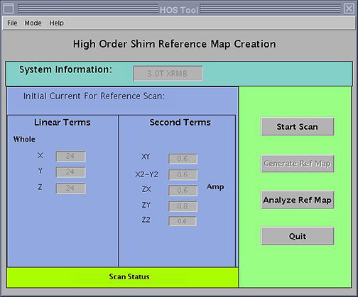
The HOS Tool interface displays.
Figure 3. HOS Tool
-
(For restricted Service Tools) Make sure the
service key is installed.
- Select Start Scan.
- When the message Scanning. Please wait Until Scan
Done! displays, click OK.
The system prescans first, then scans. There are multiple scans in this sequence with no user interaction required.
After the scan is done, the lower portion of the screen says Reference Map Creation in Progress.
- Verify that the system created the HOShim reference maps correctly. (Refer to Calibration Verification.)
Calibration Verification
Procedure
- After the HO Shim Reference Map is created, click Analyze Ref Map to verify that the calibration was successful.
After the scan is complete, click Quit to exit the screen.
- When the HOSM Ref Map Analyzer screen displays, select Ref file. Select the shim reference map you want to analyze by double-clicking that file. Select the files that do not have a suffix of .mask or .params.
- If the FOV is 24 cm or 28 cm, set FOV to SMALL. If the FOV is 48, set FOV to LARGE.
Figure 4. HOSM Ref Map Analyzer
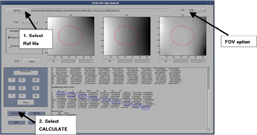
- Click CALCULATE to see data for the selected map.
- Scroll down and view the table entitled Normalized Results Mat. Review the x, x - y, y - z, z files. The values circled in blue in the illustration above should be between 0.90 and 1.0. This indicates that the HO Shim Reference Map was successfully created.
Finalization
Procedure
- Perform a SaveInfo to back up the calibration files. To verify the saved calibration files, refer to Save and Restore Tool.
- Put away all phantoms and tools.