
- Optima MR450w BASE 1.5T System Service Methods
- 5690012-2EN Revision 3
- 00000018WIA30A40940GYZ
- id_20157216.4
- Jul 5, 2021 10:36:20 PM
Installing the ICN
Installs the Image Compute Node (ICN) into the cabinet.
Prerequisites
| Personnel requirements | |||
|---|---|---|---|
| Required persons | Preliminary requirements | Procedure | Finalization |
| 1 | - | 40 minutes | - |
| Replacement parts | |||
|---|---|---|---|
| Item | Quantity | Part number | Manufacturer |
| Dell R640 (Gen7-DL) Advanced ICN with Dolphin Interface Card and GPU Card (For software version RX29.1 and later) | 1 | 5941000-11 | - |
| Safety |
|---|
|
Before working in any GE Healthcare MR suite or performing any GE Healthcare service procedure, you must:
If you have any safety concerns at any time, do not begin work or immediately stop work and move to a safe location. Immediately contact your supervisor or site safety officer for instructions on how to proceed. |
Procedure
- Connect all other cables that were previously removed to the rear of the new ICN.
Figure 1. ICN cable connections (Gen 7, Dell R640) 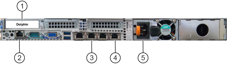
1 PCIe port (Dolphin card) 2 iDRAC (management controller for ICN) 3 Raw data server (RDS) - optional, only for research sites 4 Main switch (port 4), only 1 network cable is needed for GEN 7 and Gen 7-DL ICN 5 Power Note:Ethernet ports 1 & 3 are NOT used. Ethernet port 2 is used ONLY when the system is connected to a Raw Data Server (external to the MR System), it should be left free in all other cases. Not following this configuration may lead to VRE configuration failures and/or boot-up/TPS failures.