Installing gradient cables to the Gen2 gradient filter - scan room
Steps for preparing the scan room gradient cables for attachment to a Gen2 gradient cable with a ramped magnet.
About this task
Warning
Ferrous material hazard
The crimping tools are ferrous and should not be taken into the scan room. All cutting and crimping should be done outside of the scan room when the magnet is ramped.
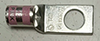
Table 1. Lugs required for this procedure
Picture
GE PN
MFG
MFG part number
Color band
Die number/ gauge
Stud size
5799023
Thomas & Betts
54155-TB
Pink
42/1/0 AWG
.500 inch
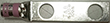
5826292
Thomas & Betts
256-30695-886
Pink
42/1/0 AWG
.500 inch
Ground gradient lug
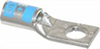
5368384
Thomas & Betts
54105
Blue
24/6AWG
.250 inch
Procedure
The end of the gradient cable must be clear of the scan room. To remove the cable from the scan room:
Note: There should be at least 50 mm (2 inches) of extra cable length to reach the connections on the gradient filter. Make sure there is enough additional cable to attach to the Gen2 gradient filter after the lugs have been replaced. If the cable length is not sufficient, a new cable must be ordered.
Pull the gradient cable through the gradient filter opening as far as possible.
If there is not enough slack in the gradient cable to pull it through the opening, disconnect the gradient cable from the busbar and shift the cable on the tray until there is enough cable to pull it through the gradient filter opening.
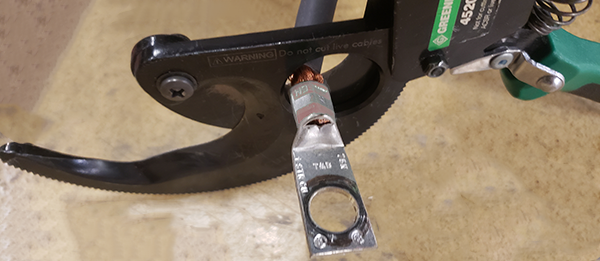
Remove the green lugs attached to the positive and negative cables on the X, Y and Z positive and negative gradient cables in the equipment room and scan room. Cut the gradient cable as close to the installed lug as possible.
Note: Do not remove the lugs from the ground cables. These will be reused.
Figure 1. Remove the lugs
From the gradient filter end of the positive cable, measure 210 mm up the gradient cable. Cut or adjust the cable lengths as needed to allow these dimensions.
Note: For instructions on the proper way to strip the gradient cable, see Stripping gradient cables.
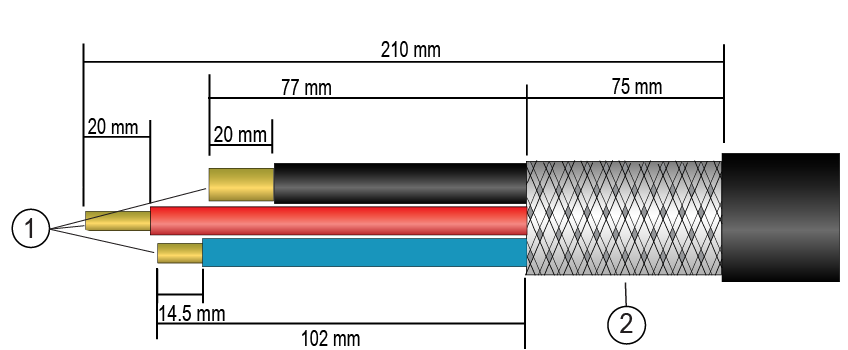
Figure 2. Stripping gradient cables
1
Wires
2
Braid
Remove the outer cable jacket up to a length of 210 mm from the cut end of the cable.
Measure and mark 75 mm from edge of outer insulation.
Remove the remaining braid from the mark to the end of each cable, exposing the two red wires, two black wires, and the ground wire.
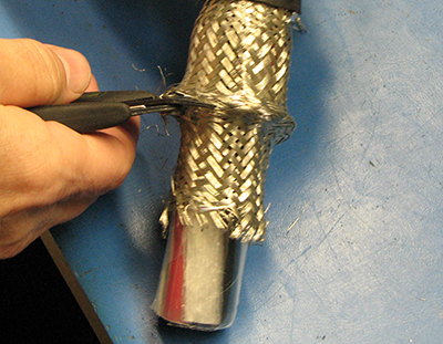
Figure 3. Cutting the braid shield
Remove the plastic covering on the braid.
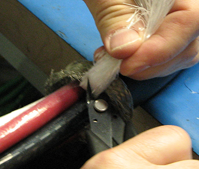
Remove the white gradient cable packing to the end of the braided shield.
Figure 4. Cable packing
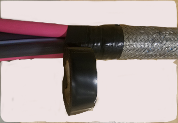
Wrap electrical tape around the end of the braid to keep the braid from unraveling.
Figure 5. Wrapping braid in tape
On the negative (black) cables, measure 77 mm from the braid (or 152 mm from the edge of the outer insulation) and cut each cable.
Discard the remaining cable.
Strip the red and black wires 20 mm from the cut end.
Note: You can also position the barrel of the lug next to the wires and mark the strip distance using the lug as shown in Stripping gradient cables.
If possible, position the gradient filter to allow the gradient cables to be dry fit to determine correct lug orientation. If dry fitting is not possible, orient the lugs on each gradient cable in the same manner, flat portions aligned in the same way to avoid the need to twist or bend the gradient cables when attaching the lugs to the gradient filter.
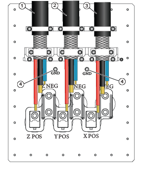
Figure 6. Gen2 gradient filter, scan room side
1
Run M3319 = FILT Z, left side
2
Run M3318 = FILT Y, middle
3
Run M3317 = FILT X, right side
For the X, Y, and Z positive gradient cables:
Note: If it is easier to remove the cables for the crimping process, dry fit and mark all cables, remove, crimp, and reinstall.
ry fit a single hole lug, 5799023, on the cable.
Align the cable with the corresponding positive connection.
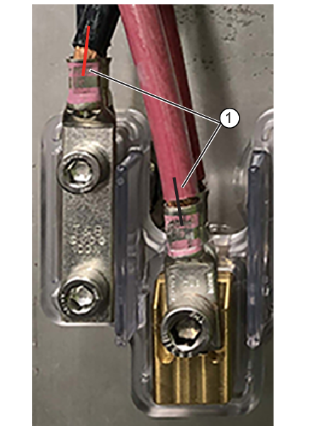
Mark the orientation of the lug to the cable.Figure 7. Dry fit and mark orientation
1
Lug orientation mark
Crimp the lug on the cable. Following the crimp instructions (see Crimping gradient cables for additional information).
Repeat with each positive gradient cable.
On the X, Y, and Z negative gradient cables:
ry fit a double hole lug, 5826292, on the cable.
Align the cable with the corresponding negative connection.
Mark the orientation of the lug to the cable.
Figure 8. Dry fit and mark orientation
1
Lug orientation mark
Crimp the lug on the cable. Following the crimp instructions (see Crimping gradient cables for additional information).