
- SIGNA™ Hero 3.0T Service Methods
- 5852800-8EN Revision 1.0
- 00000018WIA3077F450GYZ
- id_20239871.50
- Oct 19, 2021 3:26:34 PM
Installing gradient cables to the GFA2 equipment room (2nd generation gradient filter)
Attach precrimped lugs and connect the gradient cables to the equipment room side of the Gen2 Gradient Filter Assembly, 5808046-2.
About this task
Attach and secure the X,Y, and Z axis (pink lugs) to the corresponding posts, single post positive and double post negative. Torque each SHCS (socket head cap screw) to 45 Nm, using the 3/8 in. hex adapter.
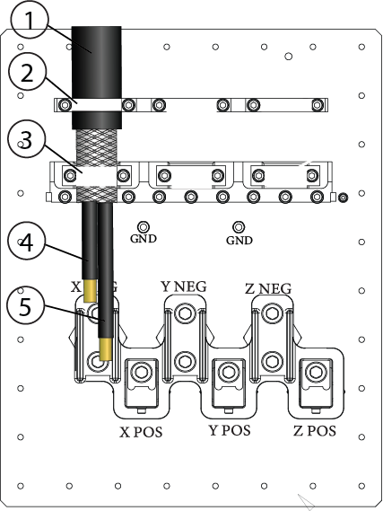
| 1 | Outer insulation |
| 2 | Upper clamp |
| 3 | Lower clamp |
| 4 | Negative wires |
| 5 | Positive wires |
Procedure
- Position the gradient cables on the corresponding clamps on the gradient filter. The black insulation should be under the top clamp, braid under the bottom clamp. Loosely secure the cables with the clamps.Note: The lower clamps are reversible. The smaller side of the clamps (1 AWG) should face inward, toward the cables.
Figure 2. GEN2 gradient filter, equipment room side 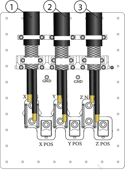
1 Run E3317 = FILT X, left side 2 Run E3318 = FILT Y, middle 3 Run = FILT Z, right side 4 Ground cable attachment locations