
- SIGNA™ Hero 3.0T Service Methods
- 5852800-8EN Revision 1.0
- 00000018WIA30F84C20GYZ
- id_20084212.19
- Jun 7, 2021 2:40:46 AM
Crimping gradient cables
Information for correct lug crimping.
About this task
Note: An optional hydraulic crimping tool (T&B TBM6PCR-LI) has been bay tested to be safe at 200 G. This tool is available for purchase directly from the manufacturer (www.tnb.com). If choosing this option, also purchase the necessary crimping dies for the tool as specified above.
Important: These steps are general crimping procedure. There may be more specific information in the procedure that requires the crimping.
Procedure
- Make sure you have the correct crimping tool. The only qualified crimpers approved for use with the Thomas and Betts Color-Keyed® lugs are the Thomas and Betts model TBM5 or TBM5-S.
Figure 1. TBM5-S crimp tool 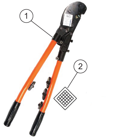
1 Crimp tool 2 Tool creates diamond style crimp - Identify the required lugs for your procedure. Consult the procedure for the correct lugs.
Table 1. Available Lugs Picture GE part number MFG MFG part number Color band Die number/ gauge Stud size 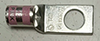
5799023 Thomas & Betts 54155-TB Pink 42/1/0 AWG .500 inch 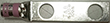
5826292 Thomas & Betts 256-30695-886 Pink 42/1/0 AWG .500 inch 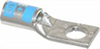
5368384 Thomas & Betts 54105 Blue 24/6AWG .250 inch - Match the color on the lug to the color on the die.Note: The die may need to be switched when crimping a different colored lug (blue ground and pink or green lugs require different dies).Note: A crimping nest with more than one color band may be used to crimp Color-Keyed® connectors matching any of the nest color bands.
Figure 3. Die 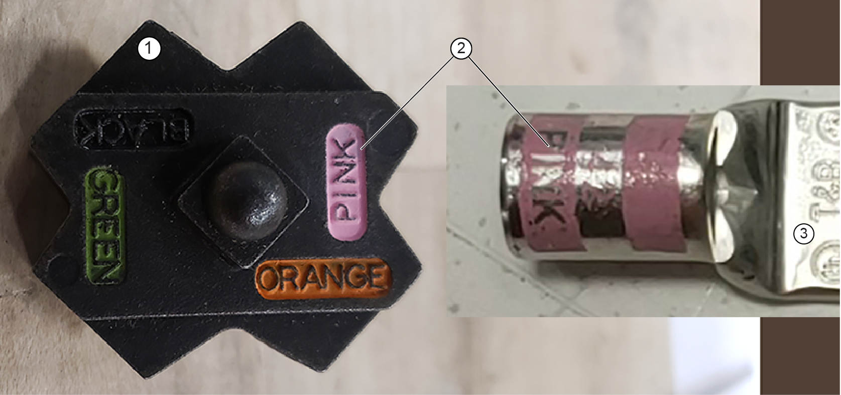
1 Die 2 Color code Table 2. Die color codes Die catalog number Die groove color Equivalent hex die code number 13454 Blue 24 13455 Green 37 - While dry fitting the lug, make sure that the:
- Cable is fully inserted in the lug.
- Insulation is not charred or melted.
- Gap from the insulation to barrel is less than the width of a two-wire bundle.
- Insulation does not extend into the barrel of the lug.
- If these conditions are not confirmed, trim the cable or insulation as needed.
Figure 4. Confirming gap and insulation clearance 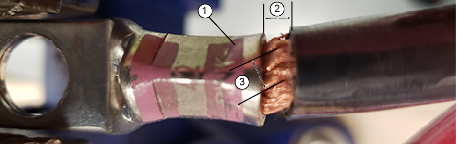
1 Barrel 2 Insulation to barrel gap (must be less than #3) 3 Two-wire bundle diameter - Put each lug in the die grooves of the crimping tool so the die is between the outer color-coded marks. Align each lug with the marks and crimp each lug onto the wires.Note: Use only the TBM5 or the TBM5-S supplied in GEHC Gradient Cable Tool Kit and the furnished T&B lugs.
Figure 5. Lug placement on crimp tool 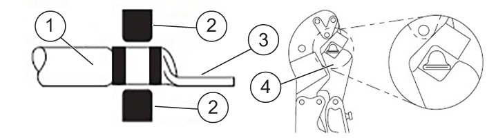
1 Wire 2 Die 3 Lug 4 Crimp tool - As each crimp is made, make sure that:
- There are no loose wire strands. All conductor strands must be contained within the conductor crimp area. Zero loose strands are allowed.
Figure 6. Good loose strand example 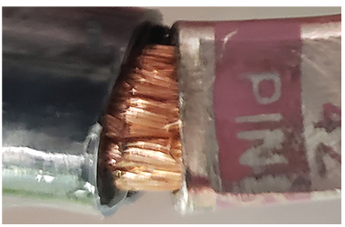
Figure 7. Bad loose strand example 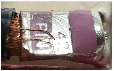
- The crimp is centered within the crimp area and the bellmouth is evident at each end of the conductor crimp area. No visible fractures or cracks should be present in the lug barrel or terminal contact mating area.
Figure 8. Good strand depth example 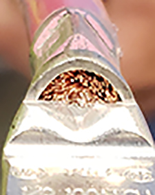
Figure 9. Bad strand depth example 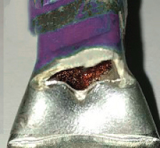
- Strand damage is within allowable parameters. The allowable strand damage as defined by IPC/WHMA-A-620C section 3.2 for Class 2 is 6%. The number of damaged (scraped, nicked, or severed) strands in a single cable should not exceed this limit. The maximum number of allowable cut strands is limited to 6% (for a 1AWG gauge wire, the maximum number of damaged strands is 50). Note: Strands that are cut off and do not continue into the lug barrel should be considered a loose strand and noted as a defect.
Figure 10. Example of 1 AWG with greater than 6% cut strands 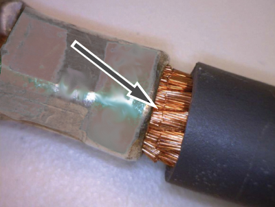
- The gap is less than the diameter of a two-wire bundle from the barrel. For an example, see Figure 4.
- Proper crimp compressions were used on the 1 AWG and 6 AWG gradient cables. Reference the next step for details.
- There are no loose wire strands. All conductor strands must be contained within the conductor crimp area. Zero loose strands are allowed.
- Do a check of the lug crimp pattern.
- For 1 AWG gradient cable (X, Y and Z axis), green bands with the printed word GREEN and the number 37 appear on the lug. The single crimp compression is diamond shaped and embossed with the number 37.
Figure 11. 1 AWG crimp pattern 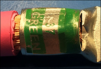
- For the 6 AWG gradient cable (ground lead), blue bands with the printed word BLUE and the number 24 appear on the lug. The single crimp compression is diamond shaped and embossed with the number 24.
Figure 12. 6 AWG Crimp Pattern 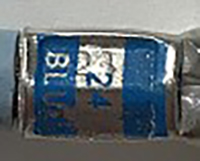
- For 1 AWG gradient cable (X, Y and Z axis), green bands with the printed word GREEN and the number 37 appear on the lug. The single crimp compression is diamond shaped and embossed with the number 37.