
- SIGNA™ Hero 3.0T Service Methods
- 5852800-8EN Revision 1.0
- 00000018WIA3073B650GYZ
- id_20251601.11
- May 14, 2020 4:31:54 PM
Connecting the gradient cables to the Gen2 gradient filter - scan room
Connection steps for gradient cable to Gen2 gradient filter, scan room side.
Procedure
- Position the gradient cables on the corresponding clamps on the gradient filter. The black insulation should be under the top clamp, braid under the bottom clamp. Loosely secure the cables with the clamps.Note: The lower clamps are reversible. The smaller side of the clamps (1 AWG) should face inward, toward the cables.
Figure 1. GEN2 gradient filter, scan room side 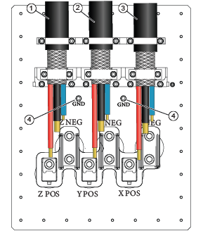
1 Run = FILT Z, left side 2 Run M3318 = FILT Y, middle 3 Run M3317 = FILT X, right side 4 Ground cable attachment locations