
- SIGNA MR355 / SIGNA MR360
- Service Manual
- 5856356-3EN Revision 5.0
- Basic Service Documentation. Copyright General Electric Company.
- 00000018WIA30141030GYZ
- id_131073011.1
- Jul 5, 2019 10:25:11 PM
MIC with cable Replacement
Prerequisites
| Required persons | Preliminary requirements | Procedure | Finalization |
|---|---|---|---|
| 1 | Not Applicable | 60 minutes | Not Applicable |
| Item | Quantity | Effectivity | Part number | Manufacturer |
|---|---|---|---|---|
| Non Magnetic Tool Set | 1 | - | - | - |
| Item | Quantity | Effectivity | Part number | Manufacturer |
|---|---|---|---|---|
| MIC with cable (Refer to Illustrated Parts) | 1 | - | - | - |
| ||||||||
| Condition | Reference | Effectivity |
|---|---|---|
|
Move the LPCA to rear pedestal with IN button of magnet front panel. Then, Separate LPCA from cradle. | - | - |
|
System Power must be turned OFF. Refer to Lockout / Tagout for System Cabinet PDU Main Breaker. | - | - |
Procedure
- Remove the two Track End Part from Track Assy.
Figure 1. Two Track End Parts 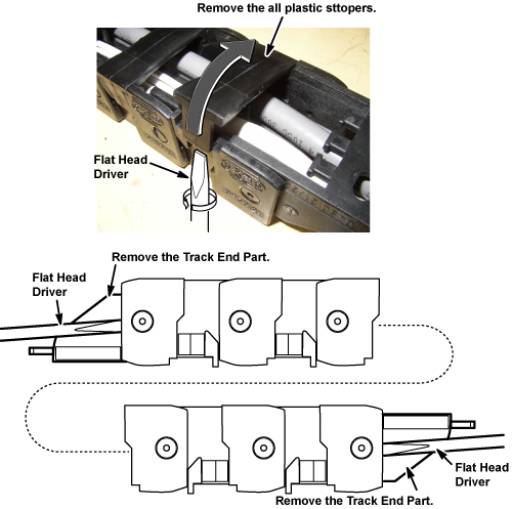
- Cut tie wraps from the each end of track assy.
Figure 2. Cut tie wraps 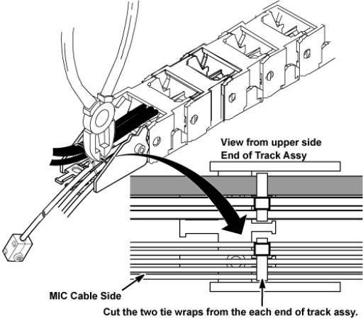
- Restore Cable and Track Assy by the reverse order of the removal.Note:
Fix the MIC cable length at 160 mm from tie-wrap point.
Figure 3. MIC cable length of LPCA side 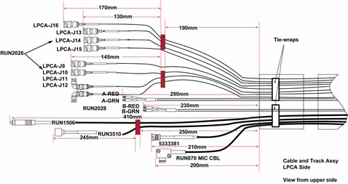 Note:
Note:Connect the LED cable so that the cable is centered to the LED itself.
Figure 4. 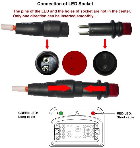
Finalization
- Restore the Power. Refer to Lockout / Tagout for System Cabinet PDU Main Breaker.
- Check intercom function. Basically, intercom adjustment of GOC Audio Box is not required. If necessary, perform Intercom Adjustment for GOC Audio Box as troubleshooting.
- Perform MCR test.
- Perform Signal to Noise - Head Scan.