
- SIGNA MR355 / SIGNA MR360
- Service Manual
- 5856356-3EN Revision 5.0
- Basic Service Documentation. Copyright General Electric Company.
- 00000018WIA3033FF20GYZ
- id_131074191.1
- Jul 5, 2019 10:46:04 PM
B Port Coil Connector Replacement
Prerequisites
| Required persons | Preliminary requirements | Procedure | Finalization |
|---|---|---|---|
| 1 | Not Applicable | 60 minutes | Not Applicable |
| Item | Quantity | Effectivity | Part number | Manufacturer |
|---|---|---|---|---|
| Non Magnetic Tool Set | 1 | - | - | - |
| Item | Quantity | Effectivity | Part number | Manufacturer |
|---|---|---|---|---|
| B Port Coil Connector (Refer to Illustrated Parts) | 1 | - | - | - |
| ||||||||
| Condition | Reference | Effectivity |
|---|---|---|
|
Move the LPCA to rear pedestal with IN button of magnet front panel. Then, Separate LPCA from cradle. | - | - |
|
System Power must be turned OFF. Refer to Lockout / Tagout for System Cabinet PDU Main Breaker. | - | - |
About this task
| Last Update | 07/08/2012 |
Procedure
- Remove LPCA Cover. Refer to LPCA Cover Removal.
Figure 1. B Port Coil Connector 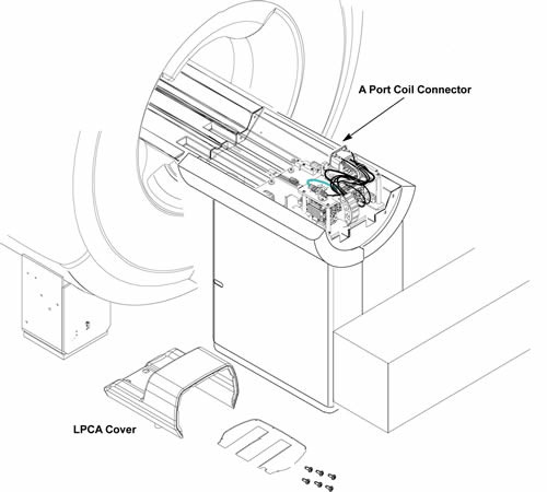
- Cut the 4 tie wraps fixing cables.
Figure 2. 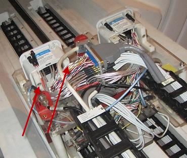
- Remove the following connectors. (BNC, J17 BNC, Sub-D Connector
J19, J20, J1 – J8 BNC connectors from MC pre-amp (Input Side) and
2 LED cable-With LED).
Figure 3. connectors 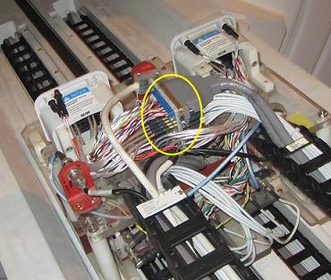
- Remove B Port Coil Connector assy from the L brackets.
Figure 4. Remove B Port Coil Connector 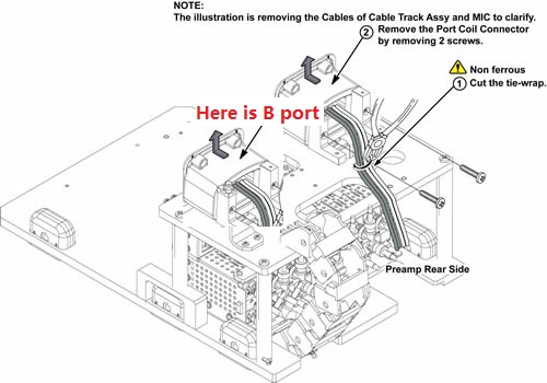
- Installation of coil port cable
Figure 5. Installation of coil port cable 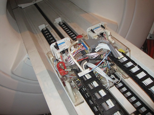
Finalization
- Restore the Power. Refer to Lockout / Tagout for System Cabinet PDU Main Breaker.
- Run MCR tool.
- Run one head or body scan.