
- SIGNA MR355 / SIGNA MR360
- Service Manual
- 5856356-3EN Revision 5.0
- Basic Service Documentation. Copyright General Electric Company.
- 00000018WIA30611030GYZ
- id_131074361.2
- Jul 5, 2019 11:19:00 PM
LPCA Assembly without cover
Prerequisites
| Required persons | Preliminary requirements | Procedure | Finalization |
|---|---|---|---|
| 1 | Not Applicable | 60 minutes | Not Applicable |
| Item | Quantity | Effectivity | Part number | Manufacturer |
|---|---|---|---|---|
| Non Magnetic Tool Set | 1 | - | - | - |
| Item | Quantity | Effectivity | Part number | Manufacturer |
|---|---|---|---|---|
| LPCA Assy without cover (Refer to Illustrated Parts) | 1 | - | - | - |
| ||||||||
| Condition | Reference | Effectivity |
|---|---|---|
|
Move the LPCA to rear pedestal with IN button of magnet front panel. Then, Separate LPCA from cradle. | - | - |
|
System Power must be turned OFF. Refer to Lockout / Tagout for System Cabinet PDU Main Breaker. | - | - |
About this task
| Last Update | 07/30/2009 |
Procedure
- Remove Bridge end cover.
Figure 1. Bridge end cover 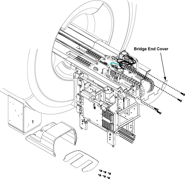
- Release the lever for the belt tension.
Figure 2. Release the lever 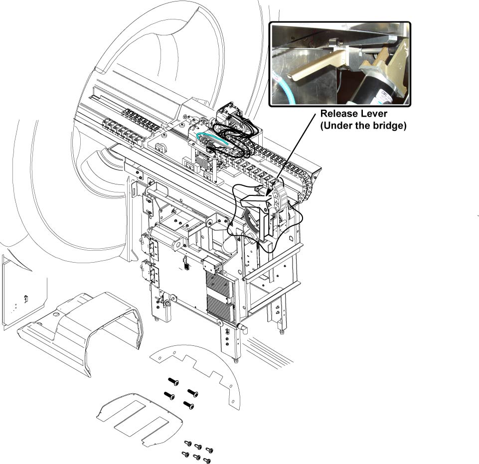
- Remove 2 belt fixture plates.
Figure 3. Removal of Belt fixture plates 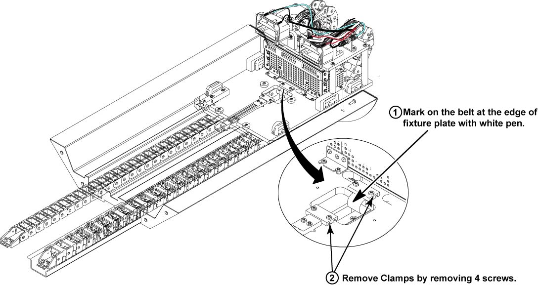
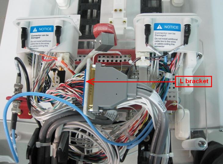
- Disconnect the all connectors from the preamp and BNC connector
bracket.
Figure 4. Disconnecting All Connectors 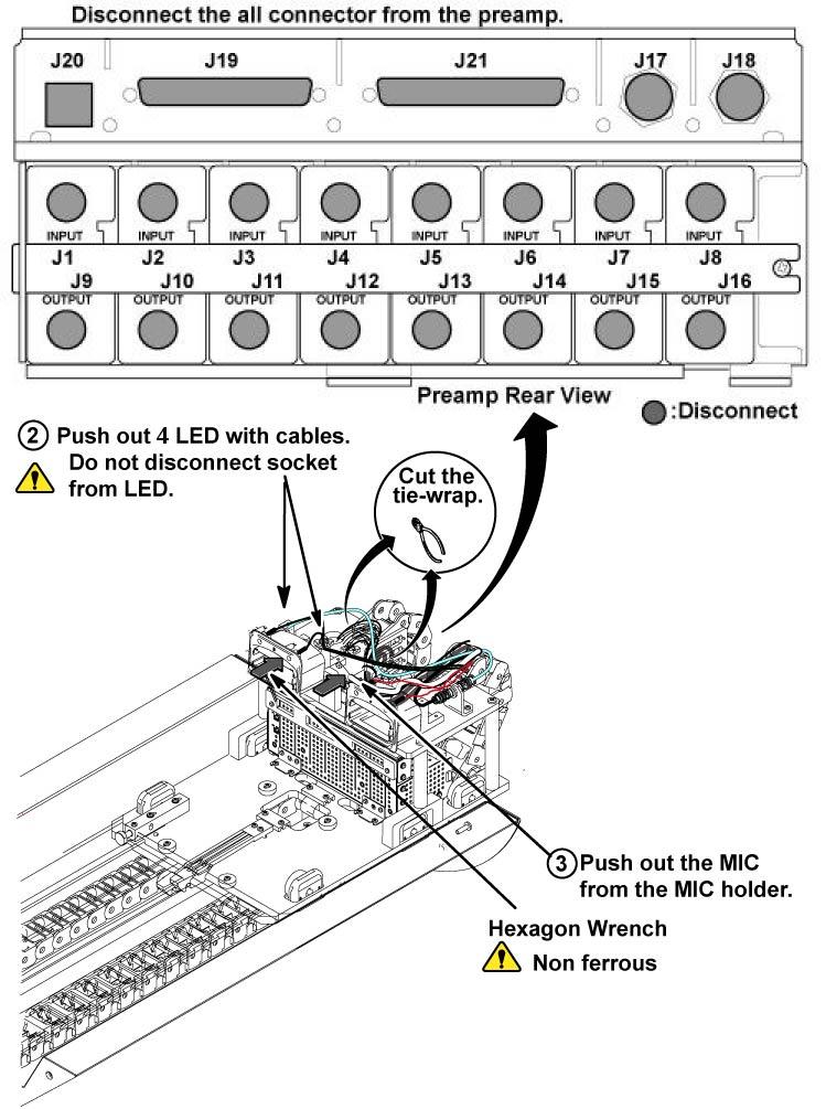
- Disconnected 3 connectors which connect B port and cables in
cable track.
- Remove A and B port coil connector assy from the bridge plate
of LPCA.Note:
A and B port coil connector reuse to new LPCA assy.
Figure 5. Removal of A Port Coil Connector 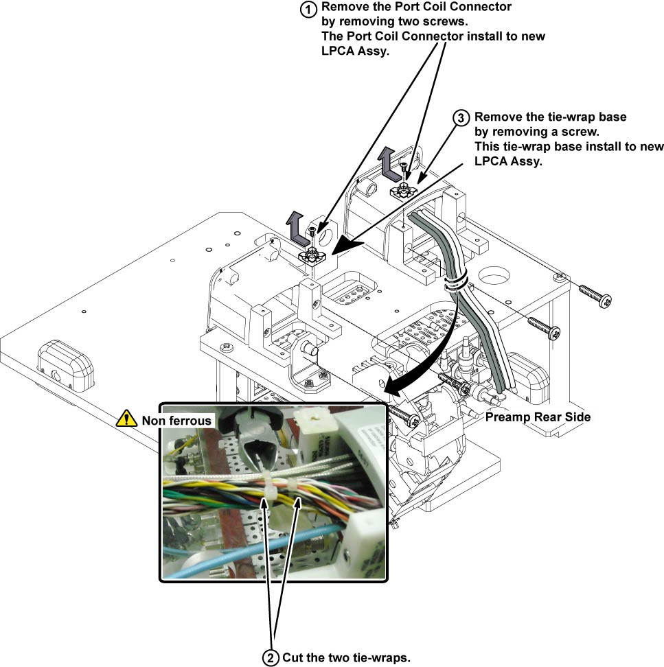
- Remove 4 screws from cable/track assy, and move the cable/track
assy to rear direction.
Figure 6. 4 screws of Cable and Track Assy 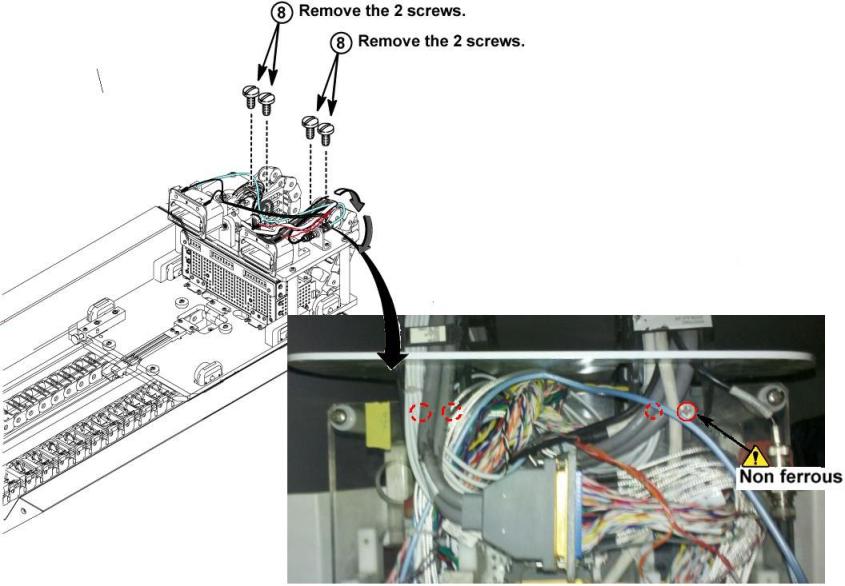
- Remove the LPCA from the Rear pedestal.
Figure 7. Remove the LPCA 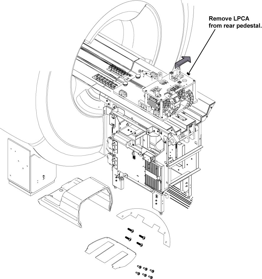
- Restore LPCA assy by the reverse order of the removal.Note:
Make sure that all the tie wraps must be fixed at the same position before removal.
Note:Connect the LED cable so that the cable is centered to the LED itself.
Figure 8. 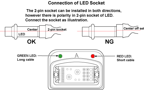
Finalization
- Restore the Power. Refer to Lockout / Tagout for System Cabinet PDU Main Breaker.
- Run MCR tool.
- Run one head or body scan.