
- SIGNA MR355 / SIGNA MR360
- Service Manual
- 5856356-3EN Revision 5.0
- Basic Service Documentation. Copyright General Electric Company.
- 00000018WIA30031030GYZ
- id_131073031.1
- Jul 5, 2019 10:25:10 PM
MC Box Chassis Replacement
Prerequisites
| Required persons | Preliminary requirements | Procedure | Finalization |
|---|---|---|---|
| 1 | Not Applicable | 60 minutes | Not Applicable |
| Item | Quantity | Effectivity | Part number | Manufacturer |
|---|---|---|---|---|
| Non Magnetic Tool Set | 1 | - | - | - |
| Item | Quantity | Effectivity | Part number | Manufacturer |
|---|---|---|---|---|
| MC Box Chassis (Refer to Illustrated Parts) | 1 | - | - | - |
| ||||||||
| Condition | Reference | Effectivity |
|---|---|---|
|
System Power must be turned OFF. Refer to Lockout / Tagout for System Cabinet PDU Main Breaker. | - | - |
About this task
| Last Update | 07/17/2009 |
Procedure
- Remove 2 screws from rear of MC Box Assy.
Figure 1. Two screws 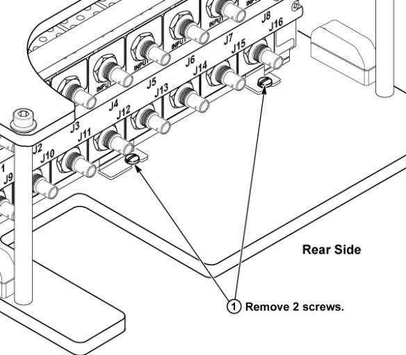
- Slide the defective MC Box Assy toward the rear side slightly
to steer clear of the belt screws and then slide towards the front
to remove it.
Figure 2. MC Box assy removal 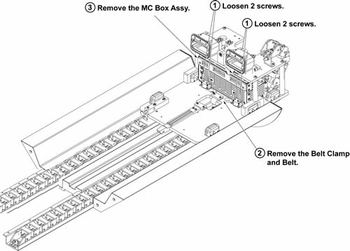
- Slide and remove the fixture bar.
Figure 3. Remove Fixture Bar 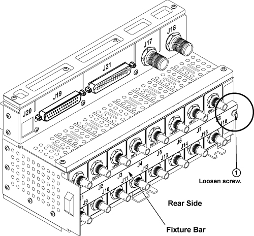
- Slide and remove all Pre-Amp.
Figure 4. Remove Pre-Amp 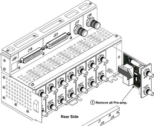
Finalization
- Restore the Power. Refer to Lockout / Tagout for System Cabinet PDU Main Breaker.
- Run MCR tool.
- Run one head or body scan.