Basic Service Documentation. Copyright General Electric Company.
Object ID: 00000018WIA3068AF20GYZ
Topic ID: id_13106101 Version: 1.7
Date: Jul 5, 2019 11:18:59 PM
Blower Box Motor Replacement
Prerequisites
Table 1. Personnel requirements
Required persons
Preliminary requirements
Procedure
Finalization
2
-
30 min (if the rear pedestal does not need
to be moved), 120 min (if the Blower Box is located at right side
of magnet room and the gap between Rear pedestal and Wall is 15.7inch
(400mm) or less) minutes
-
Table 2. Tools and test equipment
Item
Quantity
Effectivity
Part number
Manufacturer
Non-Magnetic Tool
Set
1
-
-
-
Table 3. Safety
DANGER
ELECTROCUTION HAZARD!
High VOLTAGE PRESENT IN THE BLOWER.
USE PROPER LOCK OUT / TAG OUT PROCEDURES BEFORE REPLACING
THE COMPONENTS.
Warning
POSSIBLE PERSONAL INJURY!
THIS PROCEDURE REQUIRES Movement OF highly FERROUS MATERIAL
IN CLOSE PROXIMITY TO THE MAGNET. ANY FIELD STRENGTH >200 GAUSS WILL
FORCIBLY ATTRACT THE BLOWER BOX.
STAY OUTSIDE THE 200 GAUSS LINE WHEN MOVING THE BLOWER
BOX. KEEP AS FAR FROM MAGNET AS POSSIBLE AND REFER TO MAGNETIC FIELD
SAFETY DOCUMENTATION FOR DETAILS. SEE Figure 5 FOR PROPER
METHOD for two people TO REMOVE and mount BLOWER BOX FROM MAGNET ROOM.
MULTIPLE Field engineers are required at all times.
Warning
Personal injury and equipment damage
Strong Magnetic Field
When servicing any magnetic equipment, it is critically important that the service engineer consciously plan the path to be taken when moving highly ferrous devices in the magnet environment. the path should be as far from the magnet as practical and avoid high flux-density fields.
Safety Requirements
Movement of ferrous material in the magnet room must follow the GE service procedure for that device. When exiting, move away from the magnet in the most direct manner possible. Except when moving ferrous material to and from its native location on or near the magnet, the static magnetic field in any portion of the service path shall not exceed 200 Gauss.
Two (2) MR safety trained personnel must be present at all times when servicing highly ferrous devices in the areas of magnetic fields.
When planning a service path, it is critical that the path be clear and sufficiently wide. Ensure that there are no trip hazards, obstacles, clutter, slippery surfaces or other items even partially restricting the path. If there are portable obstacles in a path, remove them from the area and replace them after the service action is completed. It is required to walk the path prior to beginning service to ensure that there is sufficient space through which to pass for yourself and the object being serviced.
Warning
Personal injury and equipment damage
Strong Magnetic Field
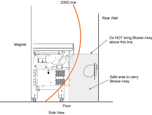
In case blower Box is located at right side of magnet room and it is necessary to path behind the rear pedestal, do not carry the blower above rear pedestal. Refer to safe area behind rear pedestal.
Notice
MATERIAL DAMAGE!
ANY FIELD STRENGTH >200 GAUSS WILL FORCIBLY ATTRACT THE MOTOR PANEL ASSEMBLY.
STAY OUTSIDE THE 200 GAUSS LINE WHEN MOVING THE BLOWER ASSEMBLY. KEEP AS FAR FROM MAGNET AS POSSIBLE AND REFER TO MAGNETIC FIELD SAFETY DOCUMENTATION FOR DETAILS.
About this task
The BRM Blower Box contains two blowers; one provides cooling
air to the gradient body coil, the other provides cooling air to the
patient comfort module. The blowers are AC induction motors. Since
they do not have brushes, the entire motor is replaced.
Even though Blower Box is located at right side, if the gap
between Rear pedestal and Wall is more than 15.7inch (400mm), go to
next section Remove Blower Box Motor Panel Assembly.
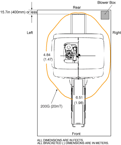
If the Blower Box is located at right side of magnet room and
the gap between Rear pedestal and Wall is 15.7inch (400mm) or less
as Figure 1, it is necessary to keep the service path first. Please proceed
following two steps.
CAUTION
Strong Magnetic Field
Before turning Rear Pedestal, the Motor Assy must be removed
before changing the Rear Pedestal Position safely according to the
linked instruction below.
Otherwise, Rear Pedestal will be attracted to the Magnet.
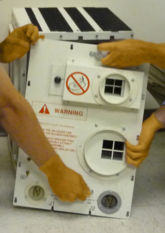
Remove the power cables, air hoses and ground cable from the
blower box. (See Figure 3.)
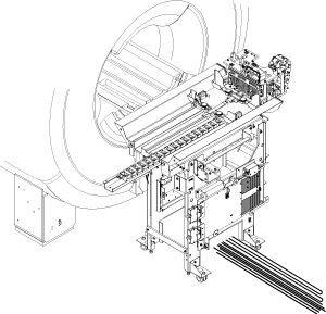
Figure 3. Blower Box
Loosen, but do not fully remove the 14 screws securing the
blower box motor panel assembly to the blower box. (See Figure 3.)
DANGER
BODILY INJURY.
ANY FIELD STRENGTH >200 GAUSS WILL FORCIBLY ATTRACT THE
MOTOR PANEL ASSEMBLY.
STAY OUTSIDE THE 200 GAUSS LINE WHEN MOVING THE BLOWER
ASSEMBLY. PLEASE KEEP AS FAR FROM MAGNET AS POSSIBLE AND REFER TO
MAGNETIC FIELD SAFETY DOCUMENTATION FOR DETAILS.
Warning
POSSIBLE PERSONAL INJURY!
DO NOT PLACE ANY PART OF THE HUMAN BODY IN THE PATH BETWEEN
THE Blower Box Motor Panel Assembly AND THE MAGNET.
CAUTION
MATERIAL DAMAGE!
ANY FIELD STRENGTH >200 GAUSS WILL FORCIBLY ATTRACT THE
MOTOR PANEL ASSEMBLY.
STAY OUTSIDE THE 200 GAUSS LINE WHEN MOVING THE BLOWER
ASSEMBLY. KEEP AS FAR FROM MAGNET AS POSSIBLE, AND REFER TO MAGNETIC
FIELD SAFETY DOCUMENTATION FOR DETAILS.
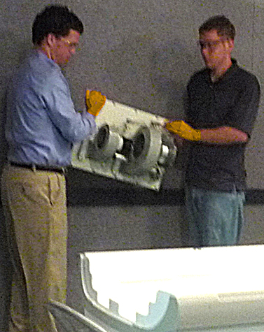
With two people holding the handles, slide the blower box motor
panel assembly up and pull it slightly away from the blower box. See Figure 4.
Figure 4. Blower Box Motor Panel Assembly – Handle with Two People
Note:
To ensure a safe distance, make sure that the clear path
through which you will be moving the blower box is completely outside
the 200G line. The distance to the 200G line can be found in the Pre
Installation Manual (PIM). (To open the PIM, from the Service Methods
media navigate to the “Pre Installation” section and select
the PIM corresponding to the system on which you are working. Gauss
plots can be found in the section titled “MR Suite Minimum Room
Size Requirements”).
THE 200G LINE MAY NOT BE WITHIN THE MINIMUM SERVICE AREA. IF
THERE IS NOT ENOUGH ROOM TO MOVE THE BLOWER BOX OUTSIDE OF THE 200
GAUSS LINE, THE MAGNET MUST BE RAMPED DOWN PRIOR TO CONTINUING.
With two people holding the motor panel assembly, exit the magnet
room by walking as close to the wall on the coldhead side of the magnet
as possible. See Figure 5.
Figure 5. Blower Box Motor Panel Assembly – Handle with two people
Replace Blower Motor
Procedure
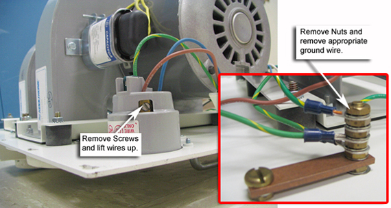
Disconnect the wiring (shown in Figure 6) from the failed motor.
Figure 6. Blower Wire Removal
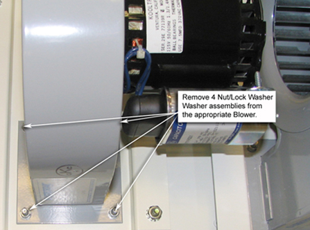
Remove the failed motor from the panel. (See Figure 7.)
Figure 7. Blower Removal
Install the replacement motor on the panel, and secure it with
4 nut/lock washer/washer assemblies.
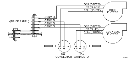
Reconnect the motor wiring. (See Figure 8.) Strip 10 to 13 mm (3/8 – 1/2 in.) of insulation from each wire.
For HOT and NEU wires, insert the wire
into the connector and tighten the set screw.
For GN1 or GN2 wires, terminate the
wire with a 6 mm (1/2 in.) ring terminal and connect it to the ground
stud.
Figure 8. Motor Panel Wiring Diagram
Install Blower Box Motor Panel Assembly
About this task
DANGER
BODILY INJURY.
ANY FIELD STRENGTH >200 GAUSS WILL FORCIBLY ATTRACT THE MOTOR PANEL ASSEMBLY.
STAY OUTSIDE THE 200 GAUSS LINE WHEN MOVING THE BLOWER ASSEMBLY. PLEASE KEEP AS FAR FROM MAGNET AS POSSIBLE AND REFER TO MAGNETIC FIELD SAFETY DOCUMENTATION FOR DETAILS.
CAUTION
MATERIAL DAMAGE!
ANY FIELD STRENGTH >200 GAUSS WILL FORCIBLY ATTRACT THE MOTOR PANEL ASSEMBLY.
STAY OUTSIDE THE 200 GAUSS LINE WHEN MOVING THE BLOWER ASSEMBLY. KEEP AS FAR FROM MAGNET AS POSSIBLE, AND REFER TO MAGNETIC FIELD SAFETY DOCUMENTATION FOR DETAILS.
Note:
To ensure a safe distance, make sure that the clear path through which you will be moving the blower box is completely outside the 200G line. The distance to the 200G line can be found in the Pre Installation Manual (PIM). (To open the PIM, from the Service Methods media navigate to the “Pre Installation” section and select the PIM corresponding to the system on which you are working. Gauss plots can be found in the section titled “MR Suite Minimum Room Size Requirements”).
THE 200G LINE MAY NOT BE WITHIN THE MINIMUM SERVICE AREA. IF THERE IS NOT ENOUGH ROOM TO MOVE THE BLOWER BOX OUTSIDE OF THE 200 GAUSS LINE, THE MAGNET MUST BE RAMPED DOWN PRIOR TO CONTINUING.
Procedure
With two people holding the motor panel assembly, stay as far
away from the magnet as possible on the coldhead side of the magnet
as you bring the motor panel assembly into the magnet room and position
it on the blower box. See Figure 5.
Reinstall the motor panel assembly, ground wire and power cable.
(Wait to reinstall the hoses until a blower check is done.)
Remove LOTO from the appropriate locations.
Reapply power to the blowers.
Verify that both blowers are operating and blowing air out of
the blower box.
Switch the breakers Off, and reinstall the blower box hoses.